Eng-Tips is the largest engineering community on the Internet

Intelligent Work Forums for Engineering Professionals

ANSYS: Beam Elements vs Joint Stiffness?

Status
Not open for further replies.

Tegguy

Aerospace
Sep 26, 2009
24
0
0
US
I'm going to apologize up front as I am not an ANSYS or an analysis expert by any means but there is some churn within our department about handling joints and I'm hoping someone can educate me.

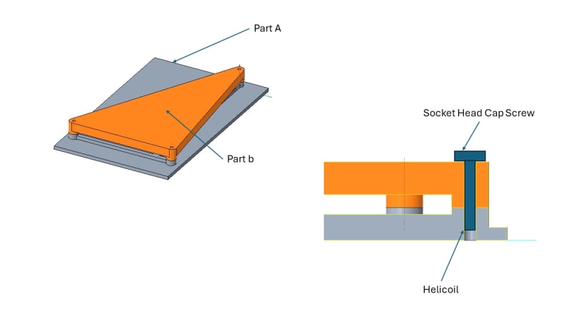
We have a bolted joint with a fastener, washer, and helicoil. The fastener is a #6 (.138) and the outside diameter of the flanges is .400 currently we are using a beam element with no preload to model this connection and I have some concerns about if this joint is taking into account the overall joint stiffness or not. Looking at contour plots of deformation it appears that there is gapping occurring at this joint which is reality wouldn't happen unless the preload was overcome.

This has lead me to a few questions:

1) Would adding preload to this joint add in the overall joint stiffness?
2) Does ANSYS allow two elements with no contact defined to pass through each other?
3) Is a beam element solely the right way to define this joint or should there be a frictionless contact or joint definition done?

I have ran a small trade study of various options (Beam element, beam element + preload, and beam element + frictionless contact) and they all yield potentially drastically different results. Ultimately we're chasing our tails with stress peaks and I'm trying to figure out if this is reality or and overly conservative model.
 
Replies continue below

Recommended for you

SWComposites said:
please show some sketches of the actual joint configurations, and how the joints are modelled in the FEMs, and I can provide some advice.

Thank you let me see what I can generate
 
SWComposites said:

Here is a quick sketch of a joint concept and you could assume a load applied at the middle of the plate. The Socket head cap screw is replaced with a beam element tied to the head contact area and the helicoil area. You can assume the Part A is restrained on the bottom surface as fixed support.

Does this give you enough information?

Joint_Concept_ccbbsb.jpg
 
1) Would adding preload to this joint add in the overall joint stiffness?
Yes. But how the socket screw is holding the part A and B? I can see that there is taping in part A and most probably the screw will be hand tightened/light torqued to some torque(Mostly < 67% or even 50% of Sy if purpose is to hold the parts together, but this is just a guess.) in to tapping threads. So applying some preload to the bolt beam is better which will be actual condition and will correctly simulate the tightened joint stiffness.
2) Does ANSYS allow two elements with no contact defined to pass through each other?
If you define parts without contact they will pass through each other like ghost, in any FEA software. You need to explicitly define in software that the parts are coming in contact to each other with respective faces.
3) Is a beam element solely the right way to define this joint or should there be a frictionless contact or joint definition done?
Beam element is quickest and crudest method to analyze bolt. The behavior will be mostly correct if physics is captured correctly and there is not much displacement of clamping parts. Adding contact in beam bolts will be unnecessary since you have already tied the ends of bolt beam to washer area and tapped hole. Socket screw will have to displace/bend much more for its shank to come into contact with hole surface.(This again depends on whether you consider root diameter or nominal diameter for bolt modelling).

If you are interested in bolt behavior and through thickness bolt stress then solid modelling with all the defined contacts is preferred.
 
NRP99 said:
Yes. But how the socket screw is holding the part A and B? I can see that there is taping in part A and most probably the screw will be hand tightened/light torqued to some torque(Mostly < 67% or even 50% of Sy if purpose is to hold the parts together, but this is just a guess.) in to tapping threads. So applying some preload to the bolt beam is better which will be actual condition and will correctly simulate the tightened joint stiffness.

Part A is tapped with a helicoil installed, part B is a thru hole. The fastener would be installed and torqued according to our internal torque spec. By applying preload does this change the behavior of the joint or just the beam element? For example would the two flanges still be allowed to pass through each other? Based on your other answer I'm assuming yes they would so the overall flange interaction seems like it might still be a little conservative.

I was thinking a good way to define a joint like this is either using a bushing element with a stiffness matrix for the overall joint or use preload + frictionless contact to capture the load sharing between the flanges but I also don't want to artificially restrain the parts in a unrealistic manner.
 
Tegguy said:
By applying preload does this change the behavior of the joint or just the beam element? For example would the two flanges still be allowed to pass through each other? Based on your other answer I'm assuming yes they would so the overall flange interaction seems like it might still be a little conservative.
Its confusing. How practically flanges pass through each other like ghost? You need to define contact between flanges(assuming you mean clamping parts), between bolt shank and bolt hole and between bolt head and part under bolt head. Without this, all parts fly or pass through each other. You need to apply preload along with above contact definition corresponding to specified torque.

Picture would be helpful to understand analysis setup.
 

Unfortunately I don't have a model and I'm not the analyst on program but this is a debate we've been having so I was trying to figure out how other people would model this. Currently they're only using a beam element with no Preload but it's causing us to chase stress areas and I think it's due to inaccuracies in the joint modeling causing a less stiff joint than we really have.

Also not factored into the analysis are two close tolerance shear/alignment pins
 
This Link might be useful for understanding bolt modelling. There are lot of articles online such as this which can be useful to understand bolt modelling.
 
NRP99 said:
This Link might be useful for understanding bolt modelling. There are lot of articles online such as this which can be useful to understand bolt modelling.

Thank you for this. I have looked at quite a few articles as well as the ANSYS learning hub training however, all the examples appear to use a gap or flexible gasket between the two flanges so there is no flange to flange interaction or load sharing and that's the piece I'm struggling to understand how to model properly or more realistically.
 
Check this article then. Specifically see figure of solid bolt contacts. For beam bolts I agree, contact between bolt and hole is not defined. But how do you transmit pre-tension between flanges(clamping parts), if there is no contact between upper flange and lower flange of bolted joint? Whether you model with solid or beam.
 
NRP99 said:
Check this article then. Specifically see figure of solid bolt contacts. For beam bolts I agree, contact between bolt and hole is not defined. But how do you transmit pre-tension between flanges(clamping parts), if there is no contact between upper flange and lower flange of bolted joint? Whether you model with solid or beam.

Thank you. I will take a look at the article provided.
 
Status
Not open for further replies.
Back
Top