lgianluca
Mechanical
- Dec 29, 2017
- 20
Dear friends,
I'm dealing with a spring sheet inserction on a tube.
I'm conducting a static structral analysis because i would understand the max stress on the spring element.
The simulation is a 2D sim. to let reduce the computing time.
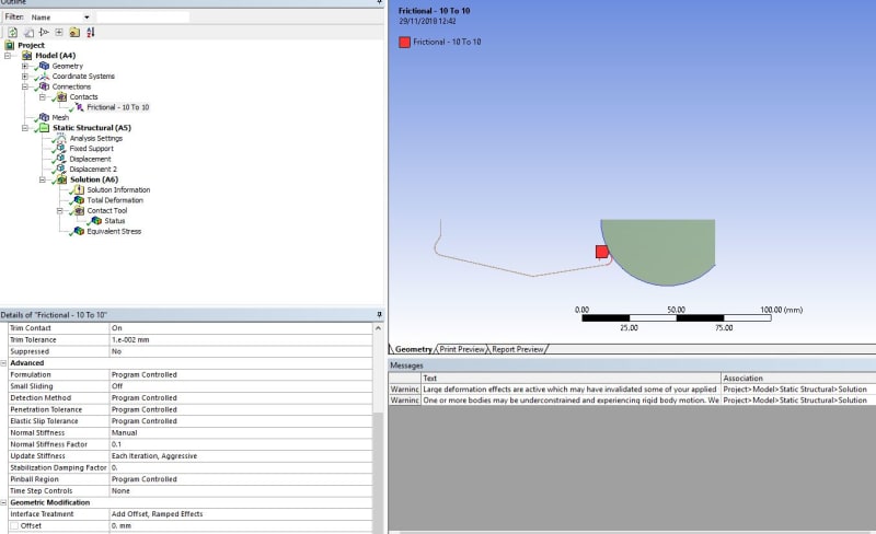
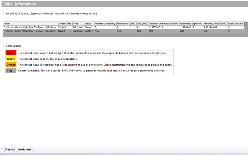
The friction contact was regularly detected (see image attached).
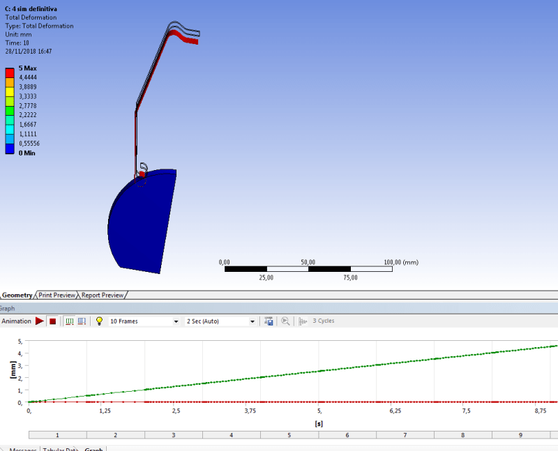
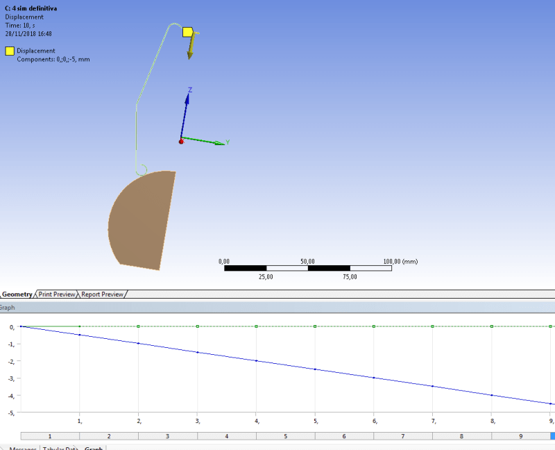
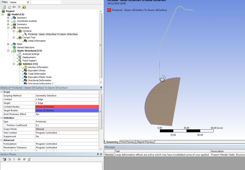
My problem is that applimg a displacement on the spring i'm not able to see the spring deformation (see results images).
Please help me because i'm loosing mi life!!!!!
Thanks friends!!
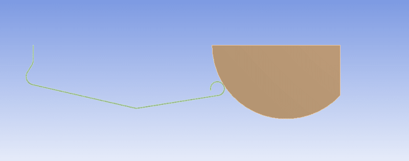
I'm dealing with a spring sheet inserction on a tube.
I'm conducting a static structral analysis because i would understand the max stress on the spring element.
The simulation is a 2D sim. to let reduce the computing time.
The friction contact was regularly detected (see image attached).
My problem is that applimg a displacement on the spring i'm not able to see the spring deformation (see results images).
Please help me because i'm loosing mi life!!!!!
Thanks friends!!