MECHENGTOM
Mechanical
- Jan 22, 2025
- 6
Hi All,
Quick background on the matter:
1. I have conducted a non-linear FEA (using ANSYS) on a super duplex stainless steel tube (Tube dimensions: 15.875mm ID and 1.00mm WT, Poisson's: 0.3, Young's Modulus = 200 GPa) representing the lateral crushing of a tube between two flat plates.
2. I concluded that a force of 52.5 kN/m produced an ovality of 3% within this specific tube. The value was validated against Roark's formulas for stress and strain - Table 9.2 formulas for circular rings.
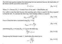
3. The plan was to use the figure of 52.5 kN/m to calculate a radius in which the tube could be bent and not exceed the 3% ovality - methodology attached.
4. The calculated radius, for the case of the previously mentioned tube was 0.193m. Tension, i.e. force to bend the tube was calculated at ~ 10 kN.
FEA Setup Overview:
- Static Structural
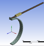
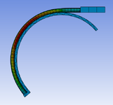
- Tube dimensions as per above. Bending profile radius as calculated above @ 0.193m. Tube guide to prevent sliding of tube across the bending profile.
- Tube non-linear material profile verified from previous FEA - same material model used for the above. 2 layers of mesh across WT with 60 divisions. Large deflections turned on.
- Frictionless contacts between tube guide to tube and tube to bending profile. Bonded contact between tube end and flat face.
- Joint rotation of 120 degrees applied to bending profile. Back tension applied to = force to bend tube @ ~ 10kN.
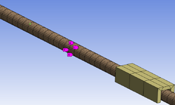
- 2 off commands entered into ANSYS solution which allows the recording of XYZ dimensions between 2 nodes (one for horizontal and one for vertical displacement). This allowed me to find the minimum and max ODs.
Results:
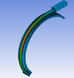
Results from the simulation are producing an ovality of 21% - in comparison to the target of 3%, this is way off. Can anyone see if there's anything fundamentally wrong with the method?
Attachments
Last edited:

