Continue to Site

Eng-Tips is the largest engineering community on the Internet

Intelligent Work Forums for Engineering Professionals

  • Congratulations KootK on being selected by the Eng-Tips community for having the most helpful posts in the forums last week. Way to Go!

Any suggestions for this reinforced concrete special moment frame? 4

Status
Not open for further replies.

user11596

Structural
Oct 28, 2022
5

So i got this short span beam generating high shear & moment which then requires increase in section size. Doing so would end up with a deep beam which i'd rather not do. Im thinking of not including the circled parts for SMF and only have those beams carry gravity loads. But how would it be constructed in actual? If i were to design those specific beams as non - ductile beam so i can get away with small cross section, concrete pouring will, i believe always incorporate a degree of fixity on the connection whether i design it as fixed or pinned. Any thoughts on this?

thank you and i hope everyone have a nice day!
 
 https://files.engineering.com/getfile.aspx?folder=922e8b6d-3f95-4c4b-9468-55055cc0f04e&file=smframe.jpg
Replies continue below

Recommended for you

Is that just because of the short end span with a long span on the other side of the support. If so, can you introduce a joint in the beam? If not, can you make the end support a short wall?

-----*****-----
So strange to see the singularity approaching while the entire planet is rapidly turning into a hellscape. -John Coates

-Dik


My suggestion will be;

- Design these two beams for gravity loads, and provide hogging reinf. for gravity loads,

- Assign hinges at both ends for seismic loading,

- Detailing as per R* Deformations,


Tim was so learned that he could name a
horse in nine languages: so ignorant that he bought a cow to ride on.
(BENJAMIN FRANKLIN )

 
Definitely don't neglect that beam in your analysis or try assume it as a gravity beam - it exists, and constructing a 'pin' in concrete is a terrible idea that won't work
You could own it, and design to suit, or take dik's suggestion and make it a wall (this has other issues in seismic though due to differing displacement characteristics of walls vs frame)

My solution though would just be to make a steel frame and design it as a gravity system
Work out your displacements at the two floor heights and impose them on the frame to work out the demands and design for that

 
@dik
Yes, so what i did was just remove the short column of two levels and have the beams cantilevered. High shear and moment on those beams was gone and the structure passed story drift checks with it removed anyways. The lowest story level by the way are ground beams. So its wall load (non bearing chb walls) acting on the ground beam part highlighted and slab and live load on the upper beam respectively. Column sizes are 550x550 mm for all and the beams in question when cantilevered are 250x350 mm. For the rest of the span, beams are 350x500 mm. Span lengths based on the shear diagram attached starting from the left is 1.5m then 3m then 4.5m then 1.5m, for your reference.

Do you think that works as well?
 
My recommendation would be the same as HTURKAK's +/-. I believe that I've actually read something similar in one of Nigel Priestley's texts on seismic design. Ideally, you'd design the the beam in question to be shallower than the other beams on that line so that the beam hinging generates lower shears on the columns. Of course, this may put you at odds with your contractor who would likely prefer a common beam cross section down the entire line of framing if possible.

Additionally, you'd want to capacity design your beam stirrups to match the hinge capacity + gravity demand to ensure that gravity capacity remains when the hingers form.

user11596 said:
Do you think that works as well?

That's clever. I do think that it would work but that wouldn't be my first choice. A cantilever is a much more fragile support than is a column. I would be loath to make that substitution just for the sake of a somewhat arcane seismic condition. It may well be that your very high beams shears would wind up uplifting your columns anyhow.
 
GreenAlleyCat said:
...it exists, and constructing a 'pin' in concrete is a terrible idea that won't work

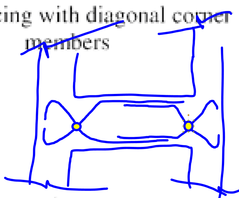
I don't agree. A "reinforcement pin" wouldn't be my first choice but, at the same time, I feel that it is a viable concept with some precedent. Heading off some objections at the pass:

a) Yes, this would hardly be a sexy, frictionless pin. Would it be enough to significantly limit seismic participation however? I think so.

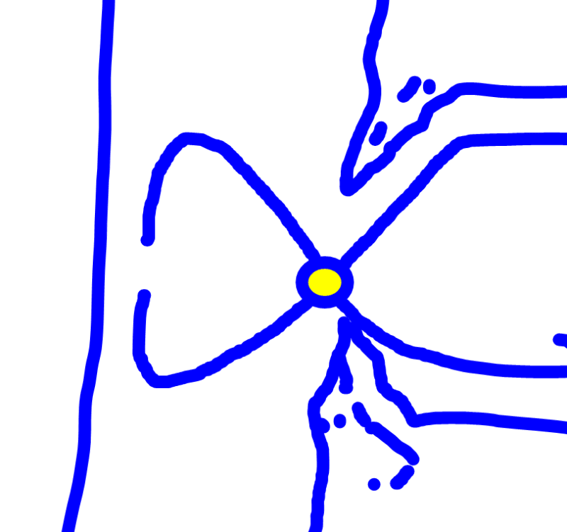
b) Yes, these "hinges" would get beat to hell in a high drift seismic event. In this respect, they'd need to be considered "consumable" as is the case with shear wall coupling beams.

c01_g133wz.png
 
I have seen that detail proposed/built before, I'm not really a fan.

You're still going to have significant moment capacity at that junction though, unless you're curtailing a lot of the steel at the joint face and only carrying enough through the joint for shear friction. Otherwise you have As,top + As,bottom all combining at mid depth of the beam which will still give a sizeable capacity. If you do curtail the steel to a minimum then it raises questions around the robustness of that joint to maintain gravity demands under significant EQ shaking.

With all the steel crossing at the mid point I can't help but feel that serviceability cracking will become more of an issue too. I'm not seeing a good reason why you would try to form this up rather than just dropping a simply-supported steel beam in there.


Yeah, there's stuff that makes it imperfect, as I acknowledged previously. Still, we're fabricating buildings, not pianos. There rarely is a "perfect".
 
GAC said:
You're still going to have significant moment capacity at that junction though, unless you're curtailing a lot of the steel at the joint face and only carrying enough through the joint for shear friction. Otherwise you have As,top + As,bottom all combining at mid depth of the beam which will still give a sizeable capacity.

Firstly, I don't see it as shear friction but, rather, as the vertical component of the diagonal bars acting as shear hangers.

Secondly, I feel that is a mischaractization of the probable moment capacity of one of these joints. When we design hinging zones to survive repeated inelastic excursions, we have to go to great trouble to confine the compression block and all that jazz to make such cyclic excursions viable. Here's we'd be doing the opposite and, after a few excursions, I'd expect our "hinge" to look something like what I've shown below. Getting more "hingey" with each cycle.

GAC said:
I'm not seeing a good reason why you would try to form this up rather than just dropping a simply-supported steel beam in there.

The reason is constructability. The introduction of a different trade, sequencing, different cladding attachments, different floor slab attachments. It's doable but it's definitely going to be weird from the perspective of the folks putting it together..

GAC said:
I'm not really a fan.

Me neither which is why I indicated that this is not my first choice. At the same time, I hardly feel that "It's a terrible idea that won't work".

c01_hwcsk1.png
 
I don't like the pin idea. I don't know if it's even allowed by modern codes. Which code are you using?

The corner column will be stiffer than the rest and could take a lot more lateral load than you think, as it tries to prop the building against seismic deformations. Short column effect. This beam is a lot more than a gravity beam and controls this behaviour.

You can make it stiffer, or ductile.

Turning the 2 columns into a wall, makes it stiffer. If it's a fixed wall, it will crack a lot. It could work if it was a pinned rocking wall, avoiding cracks. I wouldn't go with this approach tbh.

Perhaps a steel frame on the corner is not a bad idea, if you can make the two work together under EQ. It would need to be a moment frame though, not a simply supported beam (braced frame is preferable but I guess windows below). The steel beam to concrete column joint would be your new headache. The drawback is base detail, steel cost, new trades on site, etc.


@kootk, fair enough, my wording of it being a "terrible idea that won't work" was harsh and doesn't allow room for constructive discussion, sorry.
Mixing steel and concrete systems/trades is very common here so that wouldn't be any issue for us
Your point about different details for claddings etc is a good one though that I hadn't considered - something applicable to more situations than just this, worth me keeping in mind

I agree with your point about the hinge degrading over a few cycles due to lack of confinement
My concern still exists that, for the first few cycles (which tend to be the peak cycles) there will be a much larger capacity until the degradation occurs
Perhaps I worry unnecessarily though


Sometimes it is necessary to look other standards and codes .. I remembered the concept of primary and secondary seismic elements at EC-8 ( EN 1998-1) .. I copied and pasted the relevant clause below..

4.2.2 Primary and secondary seismic members
(1)P A certain number of structural members (e.g. beams and/or columns) may be designated as “secondary” seismic members (or elements), not forming part of the seismic action resisting system of the building. The strength and stiffness of these elements against seismic actions shall be neglected. They do not need to conform to the requirements of Sections 5 to 9. Nonetheless these members and their connections shall be designed and detailed to maintain support of gravity loading when subjected to the displacements caused by the most unfavourable seismic design condition. Due allowance of 2nd order effects (P-Δ effects) should be made in the design of these members.
(2) Sections 5 to 9 give rules, in addition to those of EN 1992, EN 1993, EN 1994, EN 1995 and EN 1996, for the design and detailing of secondary seismic elements.
(3) All structural members not designated as being secondary seismic members are taken as being primary seismic members. They are taken as being part of the lateral force resisting system, should be modelled in the structural analysis in accordance with 4.3.1 and designed and detailed for earthquake resistance in accordance with the rules of Sections 5 to 9.
(4) The total contribution to lateral stiffness of all secondary seismic members should not exceed 15% of that of all primary seismic members.


Tim was so learned that he could name a
horse in nine languages: so ignorant that he bought a cow to ride on.
(BENJAMIN FRANKLIN )

 
@HTURKAK the problem with that approach is that the earthquake decides a primary vs secondary member, not a Code. If you frame a concrete beam into a joint, then frame the other side of the beam into another column, you have a primary system whether you want it or not. It will massively change the way the building performs and it is not correct to ignore it unless the detailing is aligned with the theory. Which brings us back to the discussion on pin joints in concrete.


Dear Greenalleycat (Structural),

My points are,

- An experienced engineer can foresee the seismic behavior and moreover tell to structure how to behave under seismic loading. The secondary members ( columns and beams ) could be designed for gravity only loading and the contribution to seismic resistance could be neglected by assigning hinges for seismic loading case ..( eventually plastic hinges will develop at the beginning of seismic event..)

- The subject elements and their connections shall be designed and detailed to maintain support for gravity loading during seismic event and R X displacements under corresponding earthquake loads ..

- Although i am more familiar with Eurocodes , I looked to ACI 318 -19 and copy and pasted the relevant clause ,

18.14.2.1 Members not designated as part of the seismic force-resisting system shall be evaluated for gravity load
combinations of 5.3 including the effect of vertical motion acting simultaneously with the design displacement δu.

- I will suggest you to look commentary R18.14—Members not designated as part of the seismic-force-resisting system


Good Luck..


Tim was so learned that he could name a
horse in nine languages: so ignorant that he bought a cow to ride on.
(BENJAMIN FRANKLIN )

 
Sure, I completely agree that an experienced engineer can (and must) design the building to respond appropriately in an EQ. My point would boil down to, it's not about just 'assuming' that something is gravity-only - it must be detailed to suit this. The important starting point here is that a plastic hinge is NOT the same as a pin joint. A pin joint is gravity only and transfers vertical shear, no moment. This can be effectively ignored in the main lateral design in most instances. A plastic hinge will transfer both moment and shear, even after it has suffered damage from the shaking. This must be accounted for or else the design is missing critical information - say, the shear through the beam-column joint will be underestimated by ignoring the horizontal shear resulting from the bars on the side that has been assumed to be 'gravity only'.

In this case, there is a 5 storey concrete frame building. It's mostly 2 bays but steps out to 3 with the short extra bay in the bottom 2 storeys. Ignoring these extra bays in your analysis, if they are to be monolithically cast in concrete, will mean that your seismic model is fundamentally flawed. That's why I suggested building them in steel - easy to do pin joints.
 
GreenAC said:
@kootk, fair enough...

That's gracious of you. However, after a couple of sleeps and several long showers, I see that I've been too vehement in defending a solution that would be a very distant third or sixth alternative for me. As I mentioned at the top, a narrower beam that hinges under drift and is capacity designed for shear is my preferred solution.

With regard to your latest exchange with HTURKAK, I'm inclined to agree with the approach that he's been espousing. Consider:

1) It's impossible to include everything in a lateral modelling exercise. As such, it seems reasonable to set some bar below which lateral participation can be ignored.

2) My understanding of these kinds of provisions is that they generally give you two paths for a "gravity only" member:

a) Design it as though it does participate laterally OR;

b) Design it to be able to survive the story drift in the designated lateral system.

This setup, it seems to me, would satisfy your requirement for appropriate detailing. This is precisely what ACI does for gravity columns in shear wall buildings where high moment punching shear at the slab to column connections is the big scary thing.
 
GreenAC said:
That's why I suggested building them in steel - easy to do pin joints.

Can't resist:

1) Technically, your use of steel beams is a version of Dik's suggestion to provide pinned connections.

2) Strictly speaking, most typical steel beam to column connections transfer some moment too.
 
I agree completely with the underlying point - it's impossible to include everything in a lateral model and, at some point, you use rational judgement to exclude things.
As a prime example, modelling a steel gravity frame alongside a concrete frame
Even if the steel frame is fully fixed I doubt it will take meaningful load as a sway frame, and even less so one we account for the likely reality of slender posts (e.g. square sections) and the inherent slop at a 'nominally pinned' connection
I'm not claiming that my idea of a pinned connection is a unique stroke of genius to me - simply proposing that, if it were my design in my locality, I would probably just use some steel beams :)

The point of disagreement as I see it is really whether it is a valid assumption to call the extra bay of columns/beams on the lower two storeys 'gravity only'
The code exclusion that was snipped in has a requirement that the 'gravity' system must be no more than 15% of the stiffness of the rest of the structure
One way to settle this would be to model it with/without those members and see how the deflection changes
This would establish whether it falls within that code clause, it seems

Regardless though, my approach is that using a monolithic concrete frame (maintaining same beam and column sizes) in this instance is not a good call - code clauses are only words on paper and rational judgement says that the beam will try to take moment and there will be unsatisfactory damage/differing building response from that assumed in the analysis
It would not be code compliant here even if the structure was proven to be stable without that beam in my opinion

Your suggestion of stepping down to a smaller beam is a good one (presumably smaller column too) in which case it could likely be done monolithically and the joint easily designed for the much lower shear demands that the smaller beam will impose
The small beam/column will likely be so much more flexible that, in my opinion, it would be reasonable to design that as a gravity system and check it against the demands from imposed drift only
In this case it would be super easy to just chuck the smaller section sizes into the model anyway and show that it takes no load
 
Status
Not open for further replies.

Part and Inventory Search

Sponsor