Continue to Site

Eng-Tips is the largest engineering community on the Internet

Intelligent Work Forums for Engineering Professionals

  • Congratulations KootK on being selected by the Eng-Tips community for having the most helpful posts in the forums last week. Way to Go!

API 650 Appendix F Tank's Compression Roof/Shell Junction Area calculation 4

Status
Not open for further replies.

igor1212

Marine/Ocean
Feb 20, 2012
7
Dear gents,

I did design calculation for oil storage tank based on API650 (Annex F)
Input data:
Tank’s internal diameter = 34m
Design internal pressure P= 12 kPa
Roof slope 6:1
Material: ASTM A 516 GR. 70
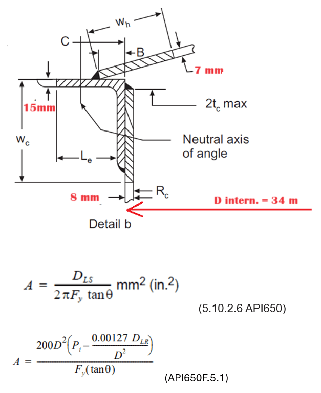
Screenshot_2024-03-18_163913_xpmlzk.png

I calculated A (Required Compression Area, Roof/Shell Junction Area as per Section F.5) for frangible roof case and got 60404 mm^2!!!
The initial idea was to make a tank with frangible roof. There is a limitation for Frangible Roof-to-Shell Junction Area Limit which cannot be exceeded (see 5.10.2.6 API650)

Frangible Roof-to-Shell Junction Area Limit is A= 8913.7 mm^2
Because Required Compression Area 60404 mm^2 is much more than Frangible Roof-to-Shell Junction Area Limit 8913.7 mm^2 frangible roof design cannot be used.
I go to non-frangible roof design and attach roof plates to the rafters and girders by welding.
The total required compression area at the roof-to-shell junction is be calculated as per API650 F.5.1 and is reduced equal to A= 58 552 mm^2

I checked all the API650 if there is any Limit for non-frangible tank’s roof designed but there is no such limitation. For your understanding initially I planned to use angle L NPL150 with dimensions 150x150mm and thickness 15mm. But Net Area at Roof/Shell Junction including 3mm Corrosion allowance would be 6660 mm^2 only and shall be increased in 10 times to pass the calculation of required compression area at the roof-to-shell junction.
So my idea is to find The biggest top angle available on the market or to weld from plates any customized angle to get required compression area at the roof-to-shell junction 58 552 mm^2.
The biggest angle which I found was equal L angle 305mmx305mm x 35mm.But even this giant super angle has 19355 mm^2 area only (and it will be reduced for CA!)

Is there any Limit for compression area at the roof-to-shell junction for non-frangible roof?
Is there any solution how to design tank 34m in diameter and 12 kPa internal pressure?
 
Replies continue below

Recommended for you

Designing a large tank for (relatively) high pressure is always going to be a problem.
First off, welding roof plate to rafters and beams is expensive and not normally done unless there is some specific reason to do so.
Also check the roof plate thickness required.
Also check anchorage and uplift required.
For the compression ring, look at using the details with a sloped flat plate (details i and j), probably easier than using a huge angle.
Increasing the roof slope reduces the area but complicates the roof structure.
We find that quite often, customers desiring high pressures like this decide they can live with lower pressures once they find the extra cost involved. People accustomed to specifying pressure vessels will throw some presumably "low" pressure out there, only to find out they are adding tens of thousands of dollars to a tank for nothing.
 
You may find that the uplift (2.4 million pounds [10.9 million N] total or 7,000 pounds per foot [102,000 N per Meter] of circumference) requires many large anchors and a foundation capable of taking the anchorage force. You do get to subtract the weight of the tank shell and roof structure attached to the shell but it will still be a consideration. The last one of these style tanks I was involved with was on a gravel and earth foundation with no suitable soils for uplift, so they added a million pounds to the tank shell, for some considerable cost. They reduced the design pressure to the minimum possible for their blanketing system and had to use multiple large pilot operated valves for their API 2000 venting.

You will have a large compression area, JStephen has valuable suggestions for you.

Good luck and let us know what yu wind up doing!
 

I just made a rule of thumb simple calculation and below my findings ,

- The roof plate shown 7 mm , and IMO, the roof should be dome, umbrella . But the roof thk. in the range of 40 mm. Even if supported cone roof is chosen (say with internal supporting truss ) welded to the roof plate , the plate thk . should be in the range of 25 mm
- The uplift which shall be resisted by foundation ( if ring foundation is chosen) requires 15 t/m weight , ( that means 2.5X2.5h m foundation size and total wt 1600 tons.
- You would need anchors with dia 40mm , spacing 1.5 m..

My suggestion would be , check your internal pressure if it is OK, consider a small internal pressure together with vapour recovery system .


He is like a man building a house, who dug deep and laid the foundation on the rock. And when the flood arose, the stream beat vehemently against that house, and could not shake it, for it was founded on the rock..

Luke 6:48

 
Dear JStephan,

You are right, 7mm roof plates thickness is not enough and it should be increased to 8mm based on API650 5.10.2.2: "Any corrosion allowance for the plates of supported roofs shall be added to the greater of the calculated thickness or the minimum thickness or [5 mm (3/16 in.) or 7-gauge sheet]." But 2mm Corrosion allowance was taken for roof plates so 7mm is OK.

Based on API650 5.10.2.6 (Frangible roof requirements):
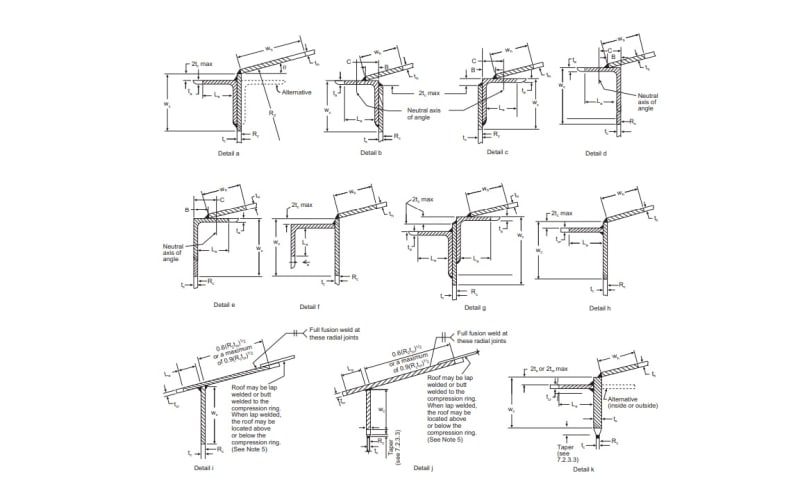
5) The roof-to-top angle compression ring is limited to details a through e in Figure F.2.
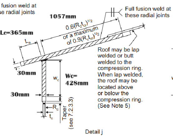
So as I understand this section of API if I will use Detail j Compression Ring design (see picture below) the design is not considered as frangible any more and I even do not have to weld rafters and girders to the shell plate?
I did calculation for detail j (I did not considered corrosion allowance for this high level calculation)
detail_j_i9lztz.png


I took wall thickness of compression ring sheet equal to 30mm. Please see on the picture dimensions which I got.
I calculated Compression Roof/Shell Junction Area as per Section F.5 and got A=59412 mm^2
So the calculation is passed! But I understand that it is very difficult to weld and bend 30mm thickness plates...
Also I can increase roof to horizontal angle. Initially it was 9 degrees. If I increase it to 12 degrees I will reduces required area ин 35%!
Is my understanding correct?
 
It appears you are designed a supported cone roof (rafters and columns).

If you make the slope greater than 1:6 (9.5°) then clause 5.10.4.3(c) says the roof plate weight can no longer be counted on to brace the rafter compression flange. This will require an alternative compression flange bracing system, or significantly larger rafters.

Increasing the slope will significantly reduce the area required (as you've already discovered). For this tank I would be considering a self-supporting dome (34m may be too large), or a stiffened self-supporting dome (I know this as an umbrella roof).

As noted by others above, you need to confirm with the Owner that this tank requires 12 kPa. As you're finding out, this is a very expensive value on such a large tank.
 
Dear IFRs,

Regarding anchor bolts and anchor chair the calculation is done. 60 anchors 56mm diameter were selected. Uplift due to design pressure, test pressure wind, seismic and it's combinations were considered and it fulfill API650 requirements.
 
Dear HTURKAK,

I used compression ring detail J (30mm thickness see my sketch above). Roof plate 7mm wall thickness (incl. 2mm CA) with compression ring detail J as per my sketch fulfill Appendix F API650 requirements. This approach is not easy to implement but it is cheaper than use of 25 mm roof plate.
 
Dear Geoff13,

Please advise what kind of alternative compression flange bracing system you are talking about.
Is my understanding correct that if I weld roof plates to the rafters and make non-frangible roof I will fulfill API650 requirement 5.10.4.3?

5.10.4.3 Structural members serving as rafters may be rolled or fabricated sections but in all cases shall conform to
the rules of 5.10.2, 5.10.3, and 5.10.4. Rafters shall be designed for the dead load of the rafters and roof plates with
the compression flange of the rafter considered as receiving no lateral support from the roof plates and shall be
laterally braced if necessary (see 5.10.4.2). When considering additional dead loads or live loads, the rafters in direct
contact with the roof plates applying the loading to the rafters may be considered as receiving adequate lateral
support from the friction between the roof plates and the compression flanges of the rafters, with the following
exceptions:
a) trusses and open-web joists used as rafters;
b) rafters with a nominal depth greater than 375 mm (15 in.);
c) rafters with a slope greater than 1:6.
 
As I noted above, I would probably switch to a self-supporting dome, or a stiffened self-supporting dome.

Welding the rafters to the roof plate would be incredibly expensive. I would estimate at least 1,500+ metres of overhead stitch welding, assuming a single span roof (centre column only). I expect this alone to increase the cost of the supported cone to be more expensive than my suggested systems.

The internal pressure will lift the roof plates, and with the rafters welded to the roof plate, these will lift as well. Assuming the framing system is welded together, including to the support column, you'll then lift the support column !!!!!! So now you need a system to keep the column returning to the proper position when the pressure is reduced. All the framing system welds must be designed for this "hanging" load condition. If you suggest that you won't weld the rafters to the rest of the framing, then what prevents the columns from falling over, and how do you accurately get the rafters to return to the same positions on the framing?

I have never designed a high-pressure tank with a supported cone roof. I have no idea how I would provide a different compression flange bracing system.

Is there a reason why you have to stay with a supported cone roof? I don't think you've mentioned how tall the tank is.
 
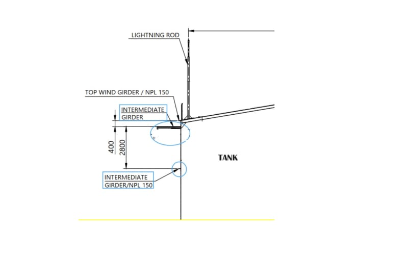
Since you are looking at the shell-to-roof joint and are not wanting it to buckle inwards from the radial component of the roof plate forces reacting to the internal pressure, would it be possible or reasonable to install a windgirder up top? It can add quite a bit of section modulus...
 
Dear IFRs,

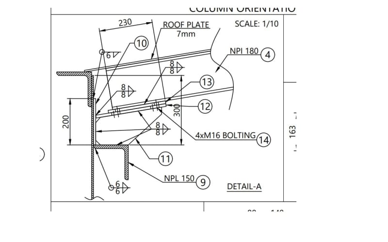
I have wind girders and even additional stiffener ring please see picture below:

roof_to_shell_junction_wdaaaa.jpg
Tank_kw6lmj.jpg


As I know if doing the calculation in accordance to API650 Annex F only specified and shown on the picture below compression ring details may be used.
So wind girders cannot be included in the Compression Area calculation. Please advise
Permisible_roof_to_shell_details_w7xhtf.jpg
 
Dear Geoff13,

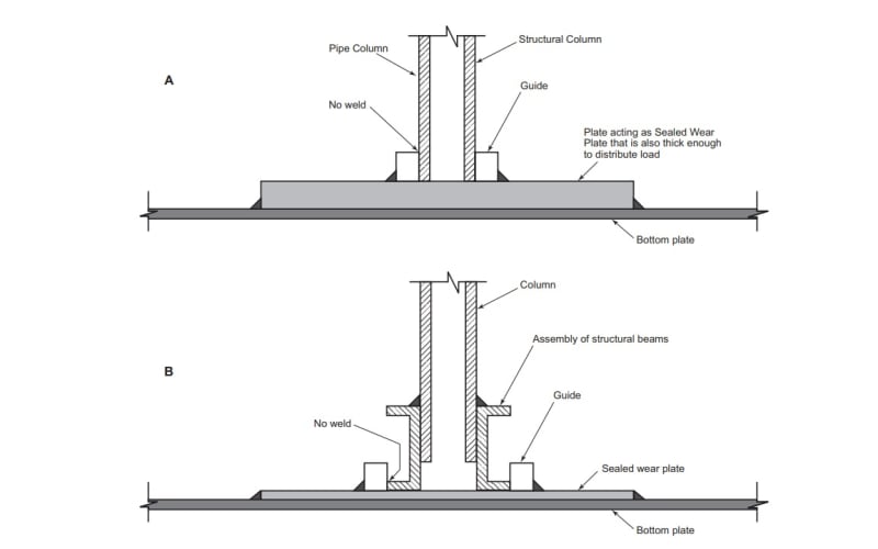
I understand your concerns regarding support column lifting. My idea was to use a guide as per API650 requirements. Please see picture below. The guide length may be increased to be sufficient for reliable column lifting.

Support_b3lnyy.jpg
 
Status
Not open for further replies.

Part and Inventory Search

Sponsor