Continue to Site

Eng-Tips is the largest engineering community on the Internet

Intelligent Work Forums for Engineering Professionals

  • Congratulations SDETERS on being selected by the Eng-Tips community for having the most helpful posts in the forums last week. Way to Go!

API 650 question 2

Status
Not open for further replies.

CWI003

Structural
Jan 4, 2010
10
Hi ,


Hi everyone ,

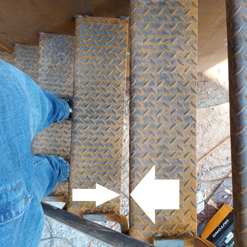
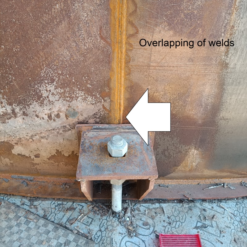
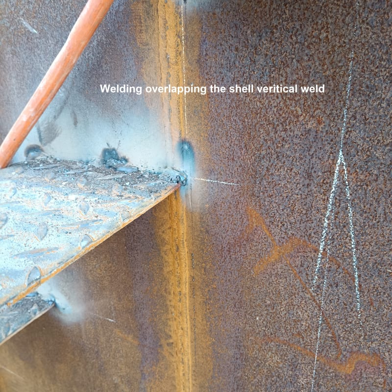
I have a question for the paragraph 5.8.1.2.a in API 650 13 th , when the anchor chair or stair is welded directly to the shell as per the pictures does it violate the code ?

also table 5.18 part 3


there are a gaps between the tread at the end so is that violating the code requirements ?

pictures attached
 
 https://files.engineering.com/getfile.aspx?folder=0f0e85da-99f7-4fdc-9cdc-2227a0d302f2&file=1670220580219_(1).jpg
Replies continue below

Recommended for you

For anyone who can't be bothered dowloading the photos

WhatsApp_Image_2023-01-10_at_12.39.01_PM_si5oso.jpg


1670220580219__1_mc4j1m.jpg


1673253371932_plhviv.jpg


They don't look great to me - Glad I'm not standing on them.

Looks like it violates 5.8.1.2 a alright for the stair tread.
It's the spot welding I don't like either...
On the anchor chair it doesn't look like the chair is welded to the shell, only the base plate?

Remember - More details = better answers
Also: If you get a response it's polite to respond to it.
 
As noted above, 5.8.1.2 is the pertinent requirement for weld spacing of attachments. However, it only applies to Groups IV, IVA, V, or VI, and this is the minority of API tanks built.
For other groups, it is good practice to lay these things out to avoid this situation, but not a requirement of the standard.

On the gap in stairs, see Item 3 in Table 5.18.

These items would normally be addressed in the drawings, not in the field.
 

- Regarding the gaps between the tread ends ,pls look Table 5.18—Requirements for Stairways as pointed out by JStephen (Mechanical) and check with local OHSA requirements


- Regarding the anchor chair, pls look
thread1452-499067

and , API 650
5.8.1.2 When attachments are made to shell courses of material in Group IV, IVA, V, or VI, the movement of the
shell (particularly the movement of the bottom course) under hydrostatic loading shall be considered, and the
attachments shall meet the following requirements:
a) Permanent attachments may be welded directly to the shell with fillet welds having a maximum leg dimension of
13 mm (1/2 in.). The edge of any permanent attachment welds shall be at least 75 mm (3 in.) from the horizontal
joints of the shell and at least 150 mm (6 in.) from the vertical joints
, insert-plate joints, thickened insert plate joints,
or reinforcing-plate fillet welds. Permanent attachment welds may cross shell horizontal or vertical butt welds
providing the welds are continuous within these limits and the angle of incidence between the two welds is greater
than or equal to 45 degrees. Additionally, any splice weld in the permanent attachment shall be located a
minimum of 150 mm (6 in.) from any shell weld unless the splice weld is kept from intersecting the shell weld by
acceptable modifications to the attachment.


Tim was so learned that he could name a
horse in nine languages: so ignorant that he bought a cow to ride on.
(BENJAMIN FRANKLIN )

 
Those are terrible welds. Also, they should be all-around for lots of reasons, not the least is to reduce corrosion issues. Crossing welds is not prohibited by API 650 for steel grades III and under but it is still a good idea. Ending an attachment weld at shell butt weld is really a bad idea from stress concentration reasons, etc. The presence of a double plate behind the anchor suggests that the anchor load are large and the shell would be over stressed, which again argues for consrvative details.
 
Good morning everyone ,


Thank you for all the replies , the welds is only tack , keep the tread in place till we approved then the fillet will be all around ,so I believe nothing can be done for the weld which intersect with the shell as the material is ASTM 36 plate , for anchor chair overlapping will be done only after the RT of that joint ? still there is more question I ll post later
 
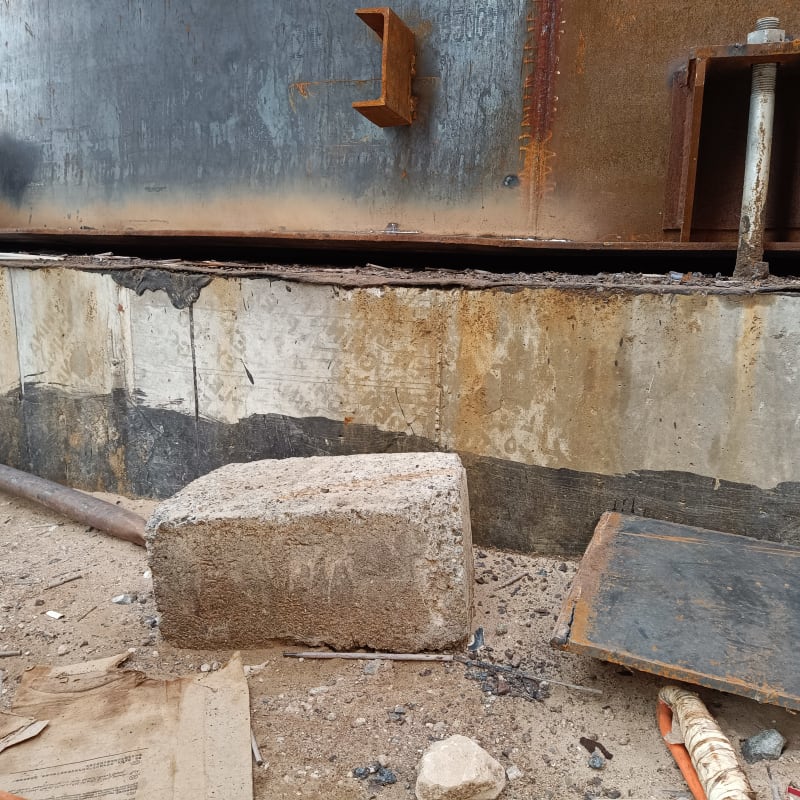
Here another issue ,the tank annular plate have a been lifted after welding ,where I can find the acceptance tolerance ? concrete foundation also have an inch out of tolerance ,sub contractor suggest to add a grout under the tank .
1673433633729_xci8vd.jpg
1673433633788_xvdolv.jpg
 
I'm a little surprised anyone has been allowed to stand on stairs which are only tacked onto the shell.

Who is running inspection and QA on this project?

Remember - More details = better answers
Also: If you get a response it's polite to respond to it.
 
Per API 650 E.7.1
Mechanically-anchored tanks shall be shimmed and grouted.
And
The annular plate thicknesses specified in API 650, as well as the width specified in 5.5.2, are based on the foundation providing uniform support under the full width of the annular plate. Unless the foundation is properly compacted, particularly at the
inside of a concrete ringwall, settlement will produce additional stresses in the annular plate
 
Is the tank fully built? Maybe this gap will reduce as more weight appears on it?

But it still looks poor workmanship.

Is there any sort of additional specification or construction spec?

Remember - More details = better answers
Also: If you get a response it's polite to respond to it.
 
Hi ,

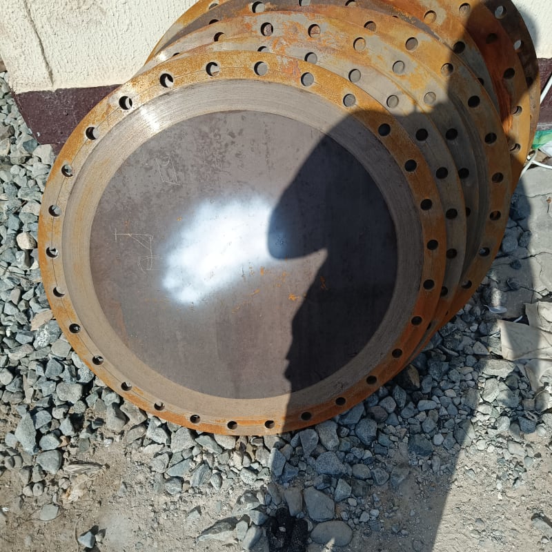
the final decision with the client ,All that observation have been recorded and forwarded to him ,API 650 13 th edition only the applicable code ,I have another question ,if ASTM 36 plate can be used for MANWAY flange and flange cover plate ,ASME 16.5 didn't listed in the table the contractor use A36 and made flanges but we didn't give the approval till now
 
A36 is generally acceptable for manway flanges and cover plates but you must make sure it meets the toughness requirement for your MDMT and the thicknesses of the parts. See sections 4.2.2.a and 4.2.9 and 4.2.10 and of course figure 4.3
 
Hi ,

thanks for your advice (IFRs's) I have checked the requirements and my understanding that we have to follow ASME 16.5 ,

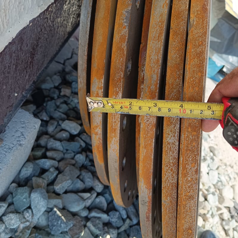
I have checked the dimension and its less than the requirement 150 class blind flange as per the table 46 mm however they are offering 18 mm machined plate for shell manway ,MDMT is 4 C .
1673851601050_nbbovy.jpg
1673851600991_k1nfbk.jpg
1673851601020_j0ckvu.jpg
 
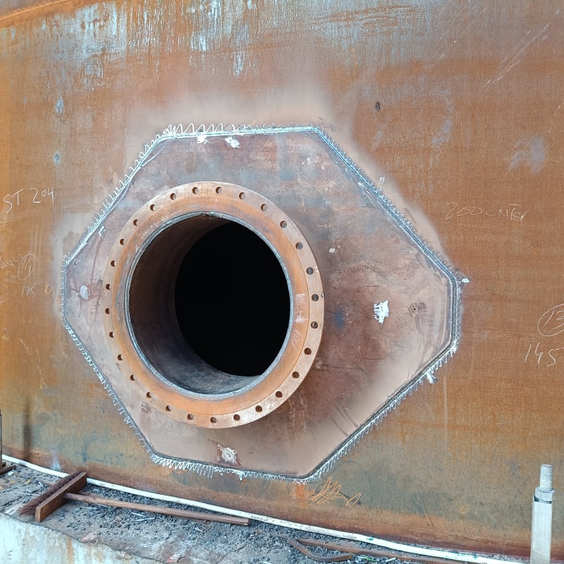
If you are building an API 650 tank and the contract is for an API 650 tank, then follow API 650 unless there is some regulatory or contractual stipulation to use another standard or code. There is no engineering reason to exceed API 650. A manway cover plate will never see pressures higher than the maximum liquid height, its thickness is governed by the stiffness needed to not leak at the bolts. There is typically no engineering reason to use 46mm cover plates if API 650 says 18mm is the correct thickness unless the tank design parameters require it. The API minimum thickness is dependent on the tank height, product density, required corrosion allowance, maximum design temperature if the tank is heated, if there will be a penetration in the manway cover plate (mixer, nozzle, etc) and if a hard gasket material is specified. See API 650 Table 5.3 for standard thickness, 5.7.5.4 for guidance on hard gaskets and 5.7.5.7 to adjust the thickness of the flange and cover if there will be a mixer. An MDMT of +4C is quite high and you will have no trouble with the material toughness if it is A36, but I would check the MDMT because a +4C MDMT suggests a lowest one-day mean temperature of about +12C which puts this tank in a very warm climate. Did the tank vendor supply approval drawings, were they reviewed by a storage tank engineer familiar with API 650? Another (3) comments from the pictures: (1) eight manways on one tank (???), (2) the radius on the cover plates looks small - it should be 6" minimum per API 650 figure 5.7 and (3) per API 5.7.5.4 it is only required to machine finish the flange (not also the cover) but it is not a bad thing as long as the minimum thickness, roughness and flatness of the flange and cover meet or exceed API 650.
 
{Did the tank vendor supply approval drawings, were they reviewed by a storage tank engineer familiar with API 650? Another (3) comments from the pictures: (1) eight manways on one tank (???), (2) the radius on the cover plates looks small - it should be 6" minimum per API 650 figure 5.7 and (3) per API 5.7.5.4 it is only required to machine finish the flange (not also the cover) but it is not a bad thing as long as the minimum thickness, roughness and flatness of the flange and cover meet or exceed API 650.}


drawing is submitted for approval ,there are many tanks not only one , I have verified the size of cover plate it have followed the required dimension in the API 650 ,thanks for the information regarding the flange and flange cover now its clear ,so the manway and cover plate doesn't required to be marked as per the ASME 16.5 ,it only applicable to the other opening .
 
You also appear to be missing a (usually thick) washer under the nut on top of the anchor chair to cover the slot, there are usually two nuts because the lower nut is only hand tight (see API 650 5.12.12).
 
By God's grace, this tank should not pass the hydro-test. Hope it isn't being skipped.

DHURJATI SEN
Kolkata, India


Good morning everyone ,

is their in 13th edition code any statement regarding the reinforcing plates telltale holes after finishing the air leak test ? shall be keep open or can be sealed ?
 
Status
Not open for further replies.

Part and Inventory Search

Sponsor