Continue to Site

Eng-Tips is the largest engineering community on the Internet

Intelligent Work Forums for Engineering Professionals

  • Congratulations GregLocock on being selected by the Eng-Tips community for having the most helpful posts in the forums last week. Way to Go!

API 650 tank hydro test for internals

Status
Not open for further replies.

RaminH

Mechanical
Sep 22, 2020
8
Hi Folks,

We are in process of hydro testing an API 650 tank, cylindrical design, 12.5-m H x 39-m DIA.

The tank has multiple chambers that are isolated from each other, imagine now one big wall of 10-m Height separating the tank into two compartments.

The isolating wall is designed for 10-m water level difference between the two sides, that means it is designed to withstand one side empty, one side full to the 10-m water Height.

Does each compartments (chamber) need to be separately hydro tested for strength verification of the wall splitting them?

API 650 remains silent for any hydro test for internal chambers even if they undergo this high pressure (like in this design) and only asks to check Shell by filling the entire tank and maintain for 24-hr minimum.

Appreciate your thoughts.

Thanks,
R
 
Replies continue below

Recommended for you


Is the second wall 10-m Height , a bund wall for the interior tank? Could be for the reason of area restriction?

Will you pls provide a sketch ?
 
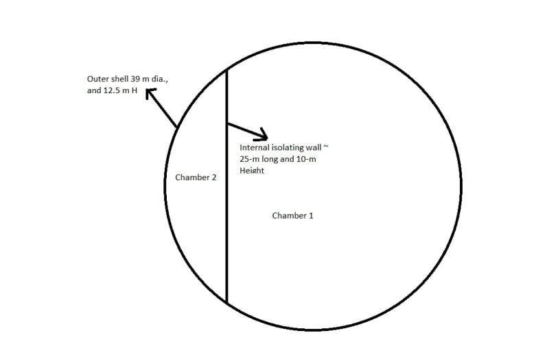
Here is the sketch, the wall splitting chamber 1 and 2 is designed for 10-m water level difference and is 10-m High too. Does Chamber 1 or 2 need to be separately hydrotested for the same 10-m high to ensure strength safety of the wall in between? The 10-m water level difference requirement for the wall between chamber 1 and chamber 2 is due to an internal process design condition for this tank.

Tank_sketch_qtg1jm.jpg
 
Where is this allowed in API 650??

Even if it does of course you need to do it both ways.

Please send us photos of the collapsed tank.

Remember - More details = better answers
Also: If you get a response it's polite to respond to it.
 
The tank has not collapsed, we want to do hydro test brand new tank now, and we were wondering if we need to hydro test each internal chamber separately (in addition to API 650 that requires full tank cylinder to be tested) to ensure the interface wall design is safe.
 

LI is right... this can be valid only both departments are full.. YOU CAN NOT EMPTY ONE OF THE DEPARTMENT !!!!If only one department is full , the system will collapse ...
 
Due to the large amount of stiffening required in the tank divider and the awkward connection details at the shell and bottom, such tanks are seldom built. (It will usually be more economical to build two separate round tanks). Consequently, API-650 doesn't address design, detailing, or testing of such tanks, and it would be a contractual matter as to how the tank was to be tested.

It occurs to me that it might be safer to test the small compartment first, as a failure of the dividing wall might hopefully be largely contained in the larger compartment. If possible, video that from a safe distance.

Edit- as a note to the above, a tank like that CAN be built, but the dividing wall will require a huge amount of stiffening to act as a beam across that span. If done properly, it's poor practicn but can be done; if done improperly, such as just a plate stretching across that span, the system will collapse or suffer large deformations when loaded.
 
Thanks folks!

The dividing wall is hugely reinforced by stiffeners and properly seal welded to the shell that is also locally reinforced to the shell/wall junction because of 10-m water level difference (wall design and junction was verified by FEA). This is not a storage tank, we have a process condition that requires one side be full and one side be empty during operation.

The question is: should this wall design condition be verified by a separate hydro test of each chamber separately, to ensure that the wall can handle 10-m level difference (to validate FEA)?

API does not request for internal walls design hydrotest, we will still do tank full hydro test as mandated by API regardless.
 

Dear Mr JStephen , did you see such a tank ? I did not see, hear, or read anywhere.. The design of circular tanks is based on the continuous hoop forces. In this case, each part of the chambers separately shall resist to hydrostatic forces as cantilever shell elements which can not be feasible..
 
HTURKAK,

The wall to shell junction on the shell is heavily reinforced for the same reason you raised, as well the wall itself is heavily reinforced, the design is checked/verified by FEA for safe operation at 10-m height level difference.

The question is should the design also be validated by a separate hydro test or no?
 
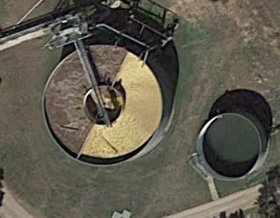
(Edited)- HTURKAK- If I remember right, we built a tank several years back, roughly 75' diameter by 16' high, with inner and outer tank, then two radial partitions between the two. So quite a bit smaller/lower, and the flat wall parts were much shorter. I believe this is it here- won't let me upload the photo directly for some reason:


Tank_vffizj.jpg
 
I agree with Jstephen that this is a contractual matter. IMO, the partition needs to be tested to confirm its strength and serviceability. It will be too late if the wall fails during operation.


This tank can not be designed with API 650 standard. How did you calculate the shell thicknesses ? will you please share the shell plate thicknesses for Courses ?


Will you please share the deflected shape for each separate loading ? I suspect that, the shell thickness designed using developing circular hoop forces as pointed at API 650 5.6. If this is the case, the tank will badly ovalize moreover could rupture during separate testing of the chambers..

Will you please post the tank pictures from inside of the chambers ?

I wish you should have posted this thread before start of the design .


Dear Mr JStephen , the picture that you have posted implies, clarifier picture (in general RC buried tank ) rather than API ground supported storage tank..


RaminH.

You've discovered that you should have told us everything at the start.

AFAIK, API650 does not allow what you are doing and therefore you don't have an API650 tank, you have a tank which you've designed based on first principles and apparently some detailed FEA of this very strange inner wall.

I also don't understand why you're now apparently trying to skimp on the testing of this unique design.

OF COURSE you need to test both sides at max height differential. All the stresses are reversed so what might be OK in one direction may well be completely different in another direction. Why on earth does anyone think differently?? you do tests in substances like water to make sure that the item in question can withstand all possible forces and modes of operation causing the highest stress and forces on the structure.

It might be that the biggest force / stress is when the whole tank is full of water and this very stiff wall is creating a stress concentration at the join which compromises the outer wall. I don't know - that's why you do tests.

My comment about the collapse was a little tongue in cheek as you hadn't told us anything about the wall or it's joint to the outer wall. But I wouldn't be standing close to it when you fill it if I were you.

Has this tank been built yet?

Remember - More details = better answers
Also: If you get a response it's polite to respond to it.
 
@LittleInch,

I understand your safety point, I am also of the firm opinion that chambers should be hydro tested separately to ensure the wall design and the wall/shell junction integrity and safety before tanks goes to operation.

Please note this is not a simple storage API tank, it is a process tank and the internal walls inside are for the same reason, we treat water in this tank.

So the design idea was as follow:

API calcs used for shell plates sizing where there is no internal wall welded to shell.
FEA calcs wherever there is an internal wall welded to the shell like the sketch I showed to you (special chamber design).

From FEA we realized that wall to shell junction on the shell plate should be heavily reinforced, so we have added thicker shell plates locally and lateral reinforcement bars from top to bottom inside welded to shell to ensure that end junctions are rigid and will not deform. Stresses and deformations are checked in ANSYS and they pass API allowable stresses under 10-m level difference on each side.

Also the internal wall itself is heavily reinforced by a heavy grid of horizontal and vertical reinforcement bars on the smaller chamber side for the full height of 10-m water difference for its design condition. FEA suggests that stresses and deformations are within API allowable on the wall itself as well.

API and FEA design calcs (in ANSYS) are checked by client and approved.

We have build the tank (not in operation) and we are close to hydrotest and there are discussions on what the procedure of hydrotest should be.

I have suggested API hydro test (whole tank full) as well as hydrotesting each chamber separately with 10-m water level on one side and the other side empty (to follow design condition).

I should check internally and see if I can share more sketches in this public forum for you to understand all the local reinforcements that I explained above.

Based on your comments, I conclude we should do separate hydrotest with all safety measures at site before operating the tank.

If more insight, please advise.
 
What about the floor to internal wall connection and foundation under the floor?

Allowance for settlement of the floor?

Just thinking out loud, but good you're thinking the same thoughts reference testing.

It might be a good idea to start with a whole tank hydro above the 10m level?, then slowly reduce water height in the smaller volume first until it's empty, then fill the smaller volume with water back to the 10m mark then reduce level in the bigger chamber.

If it starts going wrong you have a chance to catch it earlier I think.

Remember - More details = better answers
Also: If you get a response it's polite to respond to it.
 
@LittleInch

Thanks! You got that right!

For foundation settlement concern of the tank during hydro, the hydro procedure is asking to do full tank hydro first to the elevation of 12.5-m to ensure even settlement. Then one side chamber slowly drains to do the second phase of hydro for 10-m height level difference for the internal wall only.

 
this is such an unusual construction, you can't follow API 650 rules anymore. do what you think is the right thing to do.
boy id surprised if I was the inspector and had to step inside that tank and see that giant wall in front of me.
hopefully you have stiffened this tank correctly as well as the wall, good luck with whatever you decide.

Detailing is a hobby,
 
I think the issue is contractual. You can design cylindrical tank with internals against you requirement and ask the manufacture and test in accordance with API 650 or pressure vessel codes. Since there is no pressure involved (not talking about hydrostatic) so API 650 is selected for manufacture and test.

Assume that the designer was used FEA following the rules of design-by-analysis since there is no specific standard to design, manufacture and test for this kind of vessels. All the above comments are to be considered in the FEA as different load cases. Settlement is another issue that is related to the contruction of the foundation.
 
Status
Not open for further replies.

Part and Inventory Search

Sponsor