Continue to Site

Eng-Tips is the largest engineering community on the Internet

Intelligent Work Forums for Engineering Professionals

  • Congratulations cowski on being selected by the Eng-Tips community for having the most helpful posts in the forums last week. Way to Go!

Application of Guard Rail Load on Stairs 1

Status
Not open for further replies.

phamENG

Structural
Feb 6, 2015
7,623
Working on some shop drawing calcs for a fabricator client, and I've run into an issue that I want to take a closer look at. IBC 2015.

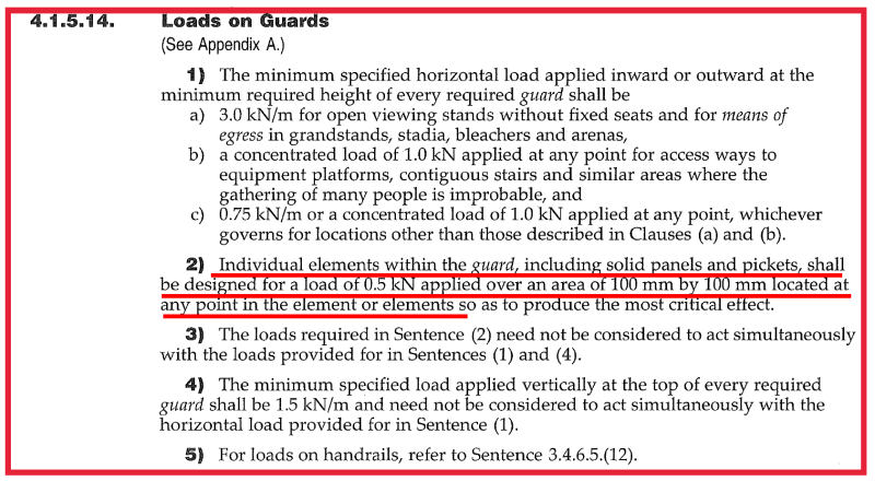
Everything I've done with this fabricator to date has been steel, but this is an aluminum project and includes guard rails - both for elevated platforms and stair rail systems (combined 42" guard with hand rail set at 36" above treads and connected to verticals on the guard). Unfortunately, it was bid and detailed like a steel system with 1-1/2 pipe at 4' on center...not even close to working. Before I go back and tell him he has to double his material, I need to sharpen my pencil a little. The architect classified this building as U, so I don't get to take advantage of the 20plf allowed for I-3, F, H, and S. 50plf and 200lbf point load.

When we apply live loads to a sloped surface (roof, ramp, stair, etc.), we apply it to the projected surface. So if you have a 100psf stair live load and a 3' wide stair with a 8' rise and 12'10" run, total live load would be 3'x12.8333'x100psf=3850lbf even though the actual sloped surface is about 15'2". The idea being that people or material occupy the vertical space above the surface and not the space perpendicular to it. Has anyone applied this concept to stair rails? So on that same stair, your rail has a run of 15'2", but the equivalent occupancy is only 12'10". In other words, you can't have enough people on the stair to apply the 50plf contemplated by a horizontal rail. So the rail would be designed for a load of about 42plf rather than the full 50.

Best bet is probably to just stick to the 50plf along the rake, but I'm curious to see if people are doing something different elsewhere.

 
Replies continue below

Recommended for you

dik - Are you saying the Canadian building code requires 51 plf, instead of the IBC's 50 plf? Are you saying you would apply a total of 51plf x 12'10" = 650 lbs? Note in phamEng's original post, 12'10" was the run of the railing.

Ron - Your position is logical, but I recall reading otherwise in the IBC. I'll dig into it tomorrow and see what I find.
 
It's from the metric conversion... actually 51.1 and a bit.

Untitled_m54iun.png


Rather than think climate change and the corona virus as science, think of it as the wrath of God. Feel any better?

-Dik
 
I’ve never done it and certainly do see your logic. Someone might argue that the code recommended line loads already account for this effect?
 

I've never encountered that argument, for any loading. Being a life safety item, I tend to be a bit more careful... like my treatment of columns and cantilevers...

Rather than think climate change and the corona virus as science, think of it as the wrath of God. Feel any better?

-Dik
 
Sorry dik, my comment was to PhamENG. I agree with you that it should be somewhat conservative. I’m questioning whether its appropriate to apply the OP’s suggested refined approach.
 
I like PhamENG’s approach.

I believe that part of our job is to make things which have always worked (practically) work with the spirit of the code.

Sometimes we structural engineers do the opposite - try to make something which has had a long history of working just fine suddenly become a problem.
 
MIStructE_IRE: I don't think they do account for it. There's no separation between stairs and horizontal guards, so there's no explicit consideration of how a sloped surface may see a different load.

In this case, it turned out to be something of a moot point. With aluminum guardrails, you can't weld be the base. Period. I tried all sorts of things - load redistribution for stiffness, messing with the loads, reducing spacing, etc....a welded 6061-T6 pipe less than 2" in diameter cannot be use if it's been welded at the base. And if you mechanically fasten it, the difference in loading doesn't make a difference. Good lesson learned on my end (I've done lots of guardrails and lots of aluminum, but this was my first aluminum guardrail).

Thanks, everyone, for participating in the thought experiment. Seems the general consensus is don't mess with it, with a few willing to push the envelope a bit.

 
IBC 2015 1607.8.1 basically refers to ASCE 7. The commentary of 1607.8.1 states these loads "are permitted to be applied independent of other loads".

ASCE 7-10 4.5.1 states the load must be "applied in any direction" to produce the maximum load effect. The commentary of 4.5.1 is not useful.

Just digging into the books a bit here, confirming both my positions:
1. No sloped bonus permitted
2. The lateral loads do not act concurrently with each other, or with any other loads including vertical loads. So if you have a channel stringer with pipe rails welded to the top flange, you're not required to design the channel for both vertical loads and the torsion from the pipe rails concurrently.
 
Mike Mike - where does it specifically disallow either of those? Or is that just your interpretation due to the absence of a clearly stated provision?
 
Generally, I would apply the 50plf to the full length of the guardrail, and apply the 200plf separately, not concurrently.
Ultimately, I think that's all been said above.

What hasn't been discussed is consideration of the NAAMM guides. They`ve done quite a bit of real world testing of these types of assemblies to quantify the benefits provided the the horizontal continuity of the rails, and stiffness provided by the end returns. Its almost a "compatibility of deflections" type argument, or the type of results you might get from an FEM type analysis. I don't have any of it in front of me, but seem to recall reductions in post loads of approximately 40%. I believe it's a free document, and definitely beneficial if you`re looking to squeeze a design like this.

 
40% reduction for middle rail with more than 2 spans, 85% for middle rail with two spans, and 82% for end rail with more than 2 spans. Doesn't matter, though, if you have to apply a 50plf load. The reduction isn't actually a reduction, just a redistribution - so it only works for point loads. The UDL gets split up based on tributary area. A true FEM analysis would provide some additional redistribution even of a UDL, but it's not enough to really consider. Where that is helpful is residential railings where there is no UDL consideration or industrial/certain institutional applications where there UDL is reduced to 20plf. Or spacing less than 4' o/c with a 50plf UDL.

Returns, on the other hand, are quite helpful in terms of strengthening the system.


I didn't see there was a 'sloped bonus' in this discussion; it just appears that some people don't consider the effect of the sloped members. For normal spacing and short cantilevers, the typical rail and post (HSS 1.66x0.125, in these environs) still works. I also use the plastic section for flexure..

Rather than think climate change and the corona virus as science, think of it as the wrath of God. Feel any better?

-Dik
 
phamENG - just my interpretation

dik - good to know you use the plastic section for flexure
 
Doesn't everyone? Most HSS sections are Class 1... and you can use Z for Class 1 and Class 2. I also check results for both calculated Mr and Mr/phiS, relying on the other components for providing added resistance... not always, but a check to see how much over it is... I don't want to do a 3D analysis of a guardrail. For endspan I use PL/5.2 as opposed to PL/4 or PL/4.9 assuming a plastic redistribution.

Rather than think climate change and the corona virus as science, think of it as the wrath of God. Feel any better?

-Dik
 
Mike Mike - ASCE 7 says not to apply the 50plf concurrently with the 200lbs, so I'm with you there, but it also says to apply the loads to produce the most unfavorable result in the component being considered AND talks about taking it through the load path. If it stopped at component, I would agree with you, but it says:

ASCE 7-10 4.5.1 Loads on Handrail and Guardrail Systems said:
...transfer this load through the supports to the structure.

Because it doesn't specifically say not to include it with the occupancy live load and it does say to carry it through to the supports that must also carry that occupancy load, I'm with Ron - the only rational approach is to apply the occupancy load on the stairs and the guardrail loading concurrently (with cases for concentrated loading and cases for horizontal loading).

dik - for steel, yes. Plastic analysis, on the other hand...well that's a bit more rare. I tried to use it when I got out of school, but all the senior engineers at the firm where I started working looked at me like I had six heads. For aluminum, the ADM requires the use of the elastic section modulus for most all calculations. I don't think they list Z in the section properties section.
 
I've used plastic design for 5 decades and haven't looked back. When I first started, I was informed that it was far more expensive... not the case... less weight and fewer pieces to handle. Sometime you are restricted to sections being Class 1 and there is no close section (but, not often). I used plastic design for Vista Cargo outside Toronto (400,000 sq.ft.); it was the first time the company I worked for had used it and there was a savings of nearly 3psf in steel from what had been estimated. Also first time the company had used HSS columns; they were of the understanding that these were more costly too... Not so, when you have 40' clear height. Phase 1 and phase 2 of the project below all using plastic design.

Clipboard01_zh0mbh.jpg


Rather than think climate change and the corona virus as science, think of it as the wrath of God. Feel any better?

-Dik
 
Is this discussion still based on aluminum?
Application of plastic analysis to welded aluminum is very limited. Welded aluminum behaves nothing like welded steel. Most aluminum grades that structural engineers use do not have the toughness or ductility to justify stable non-linear excursions. I love aluminum, but this is a fundamental limitation (unless you are using unconventional materials).

If you have zero welding anywhere near your high stress zones aluminum sections, you might be able to justify some limited non-linear (plastic) behavior.
It is more conventional for structural engineers to just stick to allowable linear elastic stresses.

If you find some solid industry-recognized work (not a PhD thesis) that says otherwise, please share - I'm ready to be converted.
 
ATSE - the original discussion was more about loading in general, but the specific case I was dealing with was aluminum.

As for industry recognized non-linear analysis of aluminum, I'm pretty sure it doesn't (and will not) exist.

 
phamENG - seems like both the codes and the discussion participants are about split on every topic we come to. according to ASCE7 I guess I should apply them concurrently. according to IBC I shouldn't. one of these days I should probably join a committee and help them with their clarity.
 
NBCC specifically excludes concurrent loading.

Rather than think climate change and the corona virus as science, think of it as the wrath of God. Feel any better?

-Dik
 
Status
Not open for further replies.

Part and Inventory Search

Sponsor