Continue to Site

Eng-Tips is the largest engineering community on the Internet

Intelligent Work Forums for Engineering Professionals

  • Congratulations KootK on being selected by the Eng-Tips community for having the most helpful posts in the forums last week. Way to Go!

Applied Base Pressure 1

Status
Not open for further replies.
Replies continue below

Recommended for you

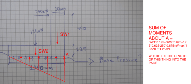
Use an equivalent point load under the base - what is the magnitude and location of a point reaction to give you equilibrium? We typically assume that these reactions are triangular, so fit a triangular reaction with the same equivalent point reaction.
 
@pharmENG

Thanks for trying to help. Can you please add some numbers on your thoughts when you find some time?
 
Generally we aren't here to do your work for you. If you look up cantilever retaining walls this is extremely common.

But I felt like being generous, so this is what Pham is alluding to

Edit: Wmax is the maximum bearing pressure directly below point A.

Edit #2 (thanks to BA): The pressure could be triangular across the full width as I've shown, it could be trapezoidal, it could be triangular over only a portion of the bottom. There isn't enough information to fully determine it. The diagram shown give you an idea of how it could be calculated when the loading is such that you have a perfectly triangular distribution that covers the entire base width (which now that I think about it more is not common at all, more of an anomoly actually).
image_ahbtkc.png
 
I don't agree with that at all. To find equilibrium, you will need to know where the horizontal force is balanced. Is it shear on the bottom? Is it passive pressure on the vertical face at the right? Is it a combination of both?

The OP has not provided enough information to determine base pressure. There is no necessity for the pressure to be triangular across the full 1250mm width of base. It could be trapezoidal or triangular over a portion of the base. We just don't know without some more information.

EDIT: I just noticed something on the left of the footing, possibly a slab. Another possible source of resistance is tension in the slab. Has the slab been reinforced to resist the applied 250kN horizontal force? Can the slab resist moment? Does the slab bring additional vertical load to the left edge of the footing? You have to look at the whole picture, not just bits and pieces.

BA
 
Jayrod12

I didn't ask you or anyone to do the work for me. I just asked a question man, there is no need to be aggressive. I am sure everyone has questions everyday at their work. Maybe my question is too daft for your level but no need to be aggressive?

Thank you for your sketch though and comments, much appreciated. Does the equation for the Wmax comes from a triangular formula?
 
The overturning moment about Point A is 250*(450+225) = 168,750kN-mm
The stabilizing moment is 125*1250/2 = 78,125kN-mm

Without some additional help, your foundation will not develop any pressure underneath it. It will simply overturn.

BA
 
Agreed BA.

Before we even get to bearing pressure we look at the statics, and the overturning moment here exceeds the restoring moment. As such, its unstable.

What’s giving you a 250kN horizontal force at the top of the wall?
 
Hi, the horizontal 250kN is a vehicle impact load and the 125kN is a wheel load.
The restoring moment should also include the whole section of the slab that's its tied with the base thickening. The idea of it is that the base thickening will be continuous and monolithic with the slab, therefore the slab area also contributes to the restoring moment.
 
Meant to send this yesterday and got distracted.

Sorry for the brevity. We often have people come here looking for free designs. That's not what we're all about. I didn't do my background check on your profile before I answered.

Yes, the Wmax in that calculation would only be for a triangular pressure distribution that perfectly took up the entire pad width. Which is actually quite rare because that means that the location of the eccentricity ends up exactly at the edge of the kern B/6.

If the load falls outside the kern, then you end up with a smaller triangle because the edge of the pad is in tension (obviously not possible with soils). If the load falls within the kern, then you end up with a trapezoidal pressure distribution.
 
BA and jayrod are spot on. My answer was meant as a first pass, not a final analysis. Your request for somebody to give you the answer gave me similar reservations to what jayrod expressed, so I was hoping to tease out a little more from you before jumping in with both feet.

If the barrier wall is tied into the slab, then I'm not sure I'd be concerned by the pressure developed by the impact load. Assuming this is all reinforced concrete, as long as the design of the wall, its connection to the slab, and the slab itself can take the impact you'd be okay. But I don't do roadway design and my knowledge of AASHTO is limited, so there may be a requirement that I'm not familiar with.
 
Status
Not open for further replies.

Part and Inventory Search

Sponsor