Continue to Site

Eng-Tips is the largest engineering community on the Internet

Intelligent Work Forums for Engineering Professionals

  • Congratulations KootK on being selected by the Eng-Tips community for having the most helpful posts in the forums last week. Way to Go!

Applying Crank Case Vacuum in single cylinder engines

Status
Not open for further replies.

michaelwoodcoc

Automotive
Jun 29, 2017
172
Hey guys, so I've considered that V8s and even inline 4's get great benefits from vacuum pumps on their engines.

I would like to apply this to a single cylinder, here's some things I'm considering:
[ol 1]
[li]The engine may provide an adequate vacuum pump for half of the crank case revolution, being a single cylinder displaces lots of air[/li]
[li]I was just going to put a check valve on the breather line[/li]
[li]The engine already has a dry sump setup. The vacuum inside the crankcase may overwhelm the ability of the high pressure low volume pump to get the oil out of the crankcase and into the oil tain[/li]
[li]if not, just a check valve combined with the high volume low pressure pump may provide vacuum through the whole crankshaft revolution[/li]
[li]the vacuum, since the volume inside the engine is not always the same, will pull the piston down through at least half of the crankshaft revolution[/li]
[li]the vacuum amount in the crankcase may be hard to measure with cheap tools since it will probably change a lot[/li]
[li]the inconsistent vacuum may not provide all of the benefits[/li]
[/ol]

I'm still curious to try. I don't have a dyno, however, just GPS data logging (10 HZ) but if the difference is big enough I can measure it.

Has this been done to anybodies knowledge? and has it been good?
 
Replies continue below

Recommended for you

Sounds reasonable. The vacuum you can achieve will depend on the crankcase volume at BDC eg if this equals swept volome, the crankcase volume will vary by a ratio of 1:2 and the best vacuum possible will be about 1/2 atmosphere.

The dry sump scavenge pump should be capable of pulling that sort of vacuum.

The energy pulling down the piston will roughly equal the energy required to push the piston up against vacuum.

Measuring the vacuum is easy. Restrict the line to the vacuum gauge with a needle valve or similar to damp out pulsation.

The benefits should be similar to a multi-cyl;inder engine.

You could augment the piston action by applying any available vacuum to the breather-check valve outlet. One example would be an exhaust ejector nozzle.

je suis charlie
 
ok one other thing that came to mind, is it possible I could actually create cavitation at the oil pump pickup tube?
I could test for this, as this particular motorcycle has an aftermarket oil filter cover made of glass. This is deffinately a test I'd prefer to complete on my spare or clunker motor.
 
If it did, you wouldn't see it at the filter. Once the oil is pressurised by the pump any vapor bubbles will condense back into the oil. One of the advantages of a vacuumed pan is removal of gas bubbles and volatiles from the oil. (removal of volatiles = lower probability of cavitation)

je suis charlie
 
The vacuum you can achieve shouldn't be directly tied to the radio of volumes. Just for discussion, if you could pull a perfect vacuum in the crankcase the pressure wouldn't change at all with the volume changes.

Otherwise, make sure your valve guides are good and tight. I find them to be the majority source of blow-by into the crankcase.
 
Most single cylinder engines create crankcase vacuum on the piston up stroke. Internal crankcase pressure is expelled through the breather on the down stroke. The breather typically has a one way valve to prevent the rapid influx of outside atmospheric pressure on the piston up stroke allowing the average crankcase pressure to be a few inches of water below atmospheric. There may be a tiny power boost but the negative pressure on the oil seals is probably the biggest benefit.
 
If it is a one cylinder motorcycle engine that has the gearbox sharing the sump (which is the usual design), the crankcase pressure fluctuation might not be all that much, due to the extra volume of air contained in the crankcases because of the gearbox.

The single cylinder engine in my little bike just has a labyrinth built into the crankcase (as-cast) to act as an oil separator, and a plain ordinary hose connecting that to the clean side of the airbox. No check valves, no PCV, no attempt whatsoever to make use of the pulsations.
 
As mentioned most singles, and 360 firing twins usually use a check valve of some sort....and others just a hose of certain length. Triumph twins used a timed breather on the inlet camshaft, venting to atmosphere, creating another oil leak, and by the '70's HC emissions. So they did away with the timed breather, and vented into the primary chaincase, giving somewhere for the pulses to go, then a simple oil trap and long hose to the rear. A much better system than the timed breather, and less oil leaks.
 
TugboatEng said:
The vacuum you can achieve shouldn't be directly tied to the radio of volumes. Just for discussion, if you could pull a perfect vacuum in the crankcase the pressure wouldn't change at all with the volume changes.


If piston action is the sole source of pumping, the maximum vacuum will be limited according to the crankcase compression ratio.

je suis charlie
 
in the motorcycle racing fraternity it was common to connect the crankcase breather to a venturi in the exhaust pipe with a reed valve in close proximity to stop oil leaks and create a negative pressure / vacuum in the crankcase

A tidy mind not intelligent as it ignors the random opportunities of total chaos. Thats my excuse anyway
Malbeare
 
^ On a related note, if the engine in question has an air-injection emission control system consisting of a reed valve on the cylinder head leading into the exhaust port (very common on anything built in the last 30 years), usually with a control valve or something in the air hose leading to it ... Eliminate the control valve and connect the crankcase vent fitting to the fitting on the head leading into the air-suction valve. The pulsations in the exhaust system when the engine is running under load will pull down the crankcase pressure. This strategy is not limited to single-cylinder applications. Don't forget to plug the two no-longer-used holes in the airbox.
 
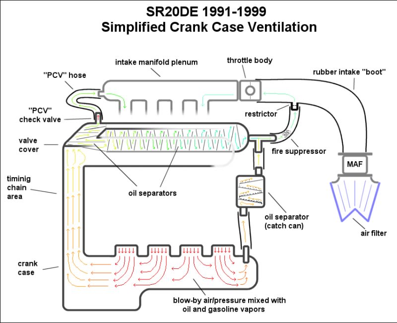
I'm confused. How does one hold a vacuum in the crankcase without eliminating it's ventilation system? The breather lets air in (filling any vacuum) and the PCV lets air out (releasing any pressure).

Crankcase_Ventilation_glgehm.jpg
 
Crankcase_Ventillation1_ndge5x.jpg
rodrico, that's a perfect diagram. Basically, you would eliminate the breather. Or put a restriction on that line. More air out than air going in is the goal.

giving credit where credit is due:
in this case there's only good crank case vacuum on engine braking, but you would still realize some benefits I'm sure. Perhaps it helps the fuel get out of the oil? not sure of the correct terminology. It was suggested to me once that it's basically to combust any blowby on decelleration, but that doesn't make much sense because there's less air to blowby on decelleration and there's less stuff in that air to need to combust.

oh guys, one thing I remember, if you have one source of vacuuming out the crank case, and you still have lots of blow by, if your vacuum point is in a valve cover, for example, and say it's a push rod v8, or something else with smaller than normal oil return passageways, the air flow to the vacuum source can cause oil puddling/pooling, and inhibit oil return. In some cases, multiple vacuum points must be utilized in order to prevent this.
 
Motorcycle engines don't (clarification: none that I've ever seen) have "positive crankcase ventilation". Forget the schematics above, they don't apply.

There is a simple hose from the crankcase (and integrated gearbox) to the airbox/air filter housing. That's it.

They usually have "pulsed air injection" as part of the emission controls. This is normally separate from the crankcase ventilation system. A hose from the airbox/air filter housing first goes to a switching valve (these days, it's an ECU-controlled solenoid valve) and then to inlets mounted on the valve covers. Underneath those inlets is a little reed-valve (spring-loaded-shut check valve) for each cylinder and it leads into the exhaust port. The extreme pressure fluctuations in the exhaust system lead to the reed-valve opening when the pressure in the exhaust port is in a negative/vacuum phase, and (if the switching valve is open) this draws a bit of air from the air filter housing into the exhaust. The purpose of this is so that under circumstances when the engine has to run rich, the extra air allows the catalyst to clean it up.

So ... Instead of routing the crankcase vent hose to the airbox, route it to the inlet of those reed valves on the valve covers. Presto, the vacuum from the exhaust pulsations is automatically check-valved and applied to the crankcase.
 
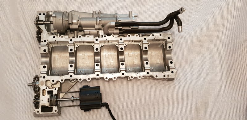
A somewhat sweeping statement, but I dont think it matters...and should still work fine - why...because on every inline 4 F1 engine I have seen each ''sump'' under its piston is separate and does not cross talk to its neighbor either - so a single cylinder as such.

You can see below on my V10 - they are separate too - although not the same as they share a bank, but same exact sump layout on the inline 4s..no comms to other cylinders, and one outlet to scavenge manifold per bank - one set of dedicated pumps/scav lobes per cylinder too.

F1V10Block_3048_nvkm9v.jpg


HTH,

Brian,
 
I doubt efficiency can be improved by selectively exploiting vacuum. First, why discriminate against pressure and use only vacuum? Both can be used to assist piston movement. In the ideal case, a pair of pistons would move 180 degrees out of phase (as in a boxer engine) so both would benefit from the vacuum and the pressure of the other. Sounds good at first glance, but the pistons are moving in unison, so there's no actual change of pressure, just movement of air. On the plus side, the work associated with moving that air is far less than the work associated with creating pressure or vacuum which could only be partially recovered if stored in a tank for later use. I just don't see efficiency gains from these approaches. Vacuum is often used, however, for horsepower gains. The article at covers the topic well.
 
I was kindof operating on the presumption that if horsepower output is improved without changing anything with the air/fuel system or air fuel ratio we must be turning more potential energy in the fuel into useful work. I've just scratched the surface though. On some engines you certainly could loose low end power and efficiency i think if the source of the vacuum is a vacuum pump that has a moment of inertia, an added belt or belt length, etc. I think if you use free sources of vacuum it may not be a problem so much.

Any advantages may be magnified with higher engine rpm. I think nascar, f1, motogp, all are predominantly operating at high RPM.

It's reassuring to see that v10 engine. I thought they mostly did this to the whole engine block on engines other than single cylinder engines.
 
Creating a vacuum does take work, so it does load the engine and affect air/fuel ratio. Imagine you have a cylinder with a piston but no head... very little work is required to push the piston in or pull it out. Now install the head... lots of work is required to push the piston in, but you get some (not all) of it back when you pull the piston out. Now install a check valve in the head the releases pressure and note it takes less work to push the piston in but more to pull it out.
 
Main reasons for wanting vac in the crankcase are to reduce the pumping losses associated with the air movement down there, and to encourage condensation (both water and fuel) to boil off. I doubt if it's worth designing and building a vacuum pump to do it, but you have a free or almost-free source of it (e.g. exhaust pulsations) you might as well use it.
 
BrianPeterson,

Yes, there are a number of reasons for wanting a slight vacuum in the crankcase. The vacuum available at the intake of a throttled engine and in the exhaust system are free because they use work that's to be wasted. Closing off the crankcase with a check valve so the pistons draw a vacuum is not free because it requires work that wasn't being wasted to make the vacuum.

Only the crazy mad folks would add a separate pump for performance reasons. These pumps are often running around 17.5" of vacuum (8.6 psig) ( and have dubious impact on performance. Tested on a 454 ci racing engine, the vacuum kit resulting in "712 horsepower at 6,900 RPM, an increase of 7 horsepower. Peak power RPM remained at 6,900. Peak torque fell by 1 ft-lbs. and didn’t reach it’s full potential until 200 RPM later at 5,600 to 577. On average, there was an increase of 6hp although average torque fell off by 2 ft-lbs." ( A average 6 HP on a 705 HP engine with a 2 lb-ft reduction in torque isn't worth the extra cost and weight IMHO.

Rod
 
Status
Not open for further replies.

Part and Inventory Search

Sponsor