Continue to Site

Eng-Tips is the largest engineering community on the Internet

Intelligent Work Forums for Engineering Professionals

  • Congratulations waross on being selected by the Eng-Tips community for having the most helpful posts in the forums last week. Way to Go!

Two-slider crank mechanism 8

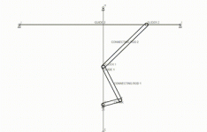
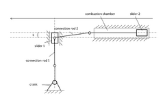
To create faster and more economical internal combustion engines, I propose to use my invention - Riyanov double-slider crank mechanism (Two-slider crank mechanism). I received 4 patents in Russia (№ 2634851), China (№ 3349271), Japan (№ 6373516) and the UK (№ 3530879) for my invention, which can be used to create more environmentally friendly and faster engines, generators or in other projects.

SUBSTANCE: crank double-slider mechanism includes a crank, two connecting rods and two sliders. The second connecting rod is connected to the first slider at one end, and to the second slider at the other end. The second connecting rod length is equal to the sum of the double crank length and the distance between the connection point of the second connecting rod with the first slider in the initial phase of its movement measured in the direction of the first slider travel and the longitudinal axis of the second slider.
EFFECT: ensured full turn of the crank in one stroke of the extreme slider in the chain in one direction.

The unconditional effect of the two-slider crank mechanism is overcoming the limitation in the number of revolutions per minute in the internal combustion engine for the same working stroke of the slider, which can be used in internal combustion engines requiring high speed (for example, drones (land, air, water), subcompact cars, motorcycles), as well as in electric generators based on internal combustion engines, wave electric generators.

The key predicted effects are a gain in speed, a reduction in fuel consumption, the use of fuel with a lower octane number as a result of an increase in the working stroke of the slider, simplicity of design (gears are not used to double the speed).

I propose to use internal combustion engines based on the proposed mechanism primarily in unmanned aerial vehicles.

The subject of discussion is the possibility of practical application of the proposed mechanism in internal combustion engines.

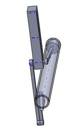
In existing internal combustion engines, the crankshaft makes half a revolution per stroke of the slider in one direction. In the proposed mechanism, it makes a full revolution per stroke of the outermost slider in the chain in one direction.Two-slider crank mechanism.jpgTwo-slider crank mechanism - animation.gif
 
Last edited:
OK then.

WHY - what thermodynamic mechanism - is the "temperature in the combustion chamber lower"? Why is this connected in any way to using a fancy linkage as opposed to a crankshaft and connecting rod? Why does the design of the mechanism underneath the piston crown make a difference to the temperature inside the combustion chamber?

Excluding heat transfer, the temperature at the end of the compression stroke is a function of the charge temperature at the beginning of the compression stroke (ideally, the intake air temperature) and the compression ratio. END. Nothing else. The path by which the piston moves in order to achieve this compression ratio and the design and layout of the mechanism that achieves it, is not relevant.

If you INclude heat transfer, then it's a very complicated function of surface area to volume ratio (bigger cylinder dimensions cause the trapped charge mass to go up with the cube of linear dimensions while the area for heat transfer goes up with the square of linear dimensions), the amount of time taken for the compression to occur (slower speed = more time for heat transfer), charge turbulence (more turbulence = more heat transfer ... keep in mind that while faster engine RPM shortens compression time, it also leads to more charge motion, so these two effects are counter each other to some complicated extent), etc.

If you are following a standard Otto (or Diesel) thermodynamic cycle - which sounds like it - then the means by which you achieve "temperature in the combustion chamber lower" are:
- Lower intake charge air temperature (intercooling, if forced induction)
- Lower compression ratio (but this is bad for the thermal efficiency of the complete cycle as a whole - and it will trend towards lowering the peak temperature but having a higher temperature at the end of the power stroke, so overall this is a "net bad" and modern engines have been trending towards as high a compression ratio as combustion chemistry and thermodynamics will let one get away with)
- Increased charge dilution, either via (cooled? common nowadays) exhaust-gas-recirculation or by running way lean (or way rich) - but running way lean is bad for NOx emissions and way rich is bad for CO and HC and both are bad for 3-way-catalyst efficiency ... and emission control is the number one consideration in engine design nowadays.

And none of this has anything to do with what the mechanism that guides the piston looks like.

So ... your turn. Explain yourself, by physical principles ... not hand-waving. There isn't much tolerance of BS explanations here.
 
One other thing. "Piston speed lower for the same rotation speed" isn't a persuasive argument. Modern piston engines normally have an upper average piston speed limit in the 20 to 25 m/s range (this is the average speed of piston motion at the engine's highest permissible operating speed - 20 m/s or thereabouts is common for run-of-the-mill engines, 25 m/s or thereabouts is for very high performance racing engines which ordinarily have greatly reduced longevity). Going higher than this range, in addition to mechanical limitations, also starts introducing fluid-flow limitations. You can connect that to the crankshaft speed by selecting the length of the stroke. And you can connect whatever crankshaft speed range you have to whatever rotation speed you need for the load, by using gears. Having a different rotation speed range relative to the piston speed, is not normally a meaningful obstacle.

Certain applications, notably piston-engine aircraft, may have the crankshaft directly connected to the load (propeller) and the operating RPM of the propeller ends up dictating some of the engine parameters. Likewise, for something like a lawnmower or weed-wacker. Or a synchronous AC generator. It doesn't seem to be a major limiting factor in any of those applications.

In automotive applications, there is always a gear-reduction between the crankshaft and the drive wheels. If you have an engine with a different engine RPM operating range, you pick a different final drive ratio.
You present confusing arguments, hiding behind facts known to you, ignoring logic. Point by point:
1. My invention has achieved a clear effect - a twofold acceleration of crank revolutions per stroke of the outermost slider in the chain without using gear transmissions. This is a fact.
2. The conclusion that the piston speed will be lower to ensure the same number of crank revolutions per unit of time is based on the fact that for the same full stroke in one direction of the outermost slider in the chain, compared to the classic crank-slider mechanism, the crank makes a full revolution (in the classic crank-slider mechanism - half).
3. The combustion rate of less flammable fuel (with a lower combustion temperature) is lower, but since the piston speed can be lower, this may be enough to ensure the same crank revolution speed. And the combustion temperature will be lower.
4. I have repeatedly pointed out that in order to draw final conclusions, research at the level of a scientific laboratory is necessary, if, of course, there is an interest in this on the part of this very scientific laboratory.
5. In accordance with the law of conservation of energy, the power of the mechanism will be less, therefore, from my point of view, it can find application, for example, in low-power engines, electric generators.
 
Last edited:
1. Why is this a benefit? What benefit does this provide to the thermodynamic cycle? How does it change anything? How does it change the P-V diagram (you know what that is, right)?
2. So let's say you want to keep the stroke and the piston speed in the same range as for a conventional engine layout when under comparable load conditions (and there are good reasons why you want to do so). Means your output shaft would be spinning half as fast. Means instead of needing (let's say) a 3:1 total drive reduction (between the crankshaft and the drive wheels), it needs 1.5:1 instead. (And now the transmission needs higher torque capacity.) What benefit is this?
3. I'm confused. Please put some numbers to this. For a point of comparison, the Chrysler Pentastar 3.6 litre 6 cylinder engine in my camper van, is geared to give 1900 rpm at 100 km/h. I'll let you look up the bore and stroke, and maximum revs, (all of this is on the internet) and figure out the piston speed at (let's say) 100 km/h cruise, and at foot-to-the-floor max-acceleration redline. Gimme some numbers for comparison.
4. OK.
5. OK, though bear in mind that the Yamaha single cylinder engine in my EF2000i generator that I use on camping trips, and in emergency in the event of long power outage, contains the following moving parts in total:
Crankshaft
Two (three if you count the one on the other end of the generator rotor) ball bearings (I'll not bother counting up the cage and balls as individual parts)
Connecting rod (two pieces bolted together around the crankshaft)
Wristpin
Piston, including two circlips to stop the wristpin escaping, and two compression rings, and the oil control ring assembly
Camshaft (driven by gears that are one-piece with the crankshaft and the camshaft)
Intake and exhaust valve lifters, pushrods, rocker arms, valve, valve spring, retainer
Cooling fan / flywheel which is bolted to the crankshaft and rotates integrally with it
Generator stator which is bolted to the crankshaft and rotates integrally with it
1. Yes, I know what a P-V diagram is. For simplicity, let's assume that the thermodynamic process is the same as in a conventional ICE with the same combustion chamber dimensions.
2. I didn't write about that. You are trying to find an increase in energy that cannot exist according to the law of conservation of energy. To put it simply, the proposed mechanism acts as a reducer that doubles the engine speed without using gears, but with a twofold decrease in torque (approximately). Therefore, it will be in demand in devices for which the speed of rotation is more important than the torque. As for the piston stroke speed, it is determined by the formula V = C * g / 30, where C is the piston stroke in meters, g is revolutions per minute, 30 is a constant for standard ICEs (half a minute), since the piston makes two movements in one revolution. With a stroke length of 0.1 meters and revolutions of 6000 revolutions per minute, we get a piston speed of 20 meters per second. In the proposed mechanism, the constant = 60, since the crank makes a full revolution in one stroke of the piston. Accordingly, the piston speed will be equal to 10 meters per second.
3. This assumption is based on a logical conclusion, a detailed analysis can be carried out using special programs and equipment based on the laboratory. In addition, this mechanism allows you to overcome the speed limitation of piston engines, which may be useful for aircraft.
4. No objections, if I understand correctly.
5. You listed the composition of the generator to show me how simple it is, if I got your point. I agree that if you constantly improve a familiar device, it will become more compact and rational. Now, until the analysis of the proposed mechanism at least at the level of a professional computer model, it is impossible to say that it will be more efficient than existing analogues. I posted this thread so that there is information about the new design and the possibility of its use, if of course there is interest in this.
I think I have clarified the situation; further correspondence will simply be a repetition of previously expressed thoughts or their detailing, which is unnecessary for specialists in this field, who will not be interested in reading the same thing from the outside.
 
Last edited:
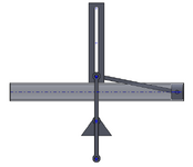
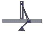
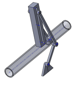
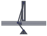
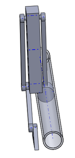
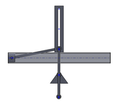
Andrey29R, your mechanism diagram and explanation of operation still leaves me with a misunderstanding: how does the working piston and its connecting rod travel the long length of the combustion chamber all while maintaining a closed cylinder? Am I totally missing the design?

I have scaled the link proportions from your schematic.

1. Piston at the start of stroke - the connecting rod from piston to the crank link must pass thru the cylinder wall.

LM1.PNG

LM2.PNG
2. Mid-stroke the connecting rod will strike the piston skirt.
LM3.PNGLM4.PNG
3. Crossing past mid-stroke the connecting rod will slice thru the piston.
LM5.PNGLM6.PNG
4. At full expansion the connecting has flipped its working angle, cut thru the piston and cylinder wall. The crank links and slider have crossed over two stall points that could cause rotation reversals to occur unless a counterweight is properly designed. I chose to show the slider as just a guided rod - having the second 'piston doesn't really provide any bearing function.
LM7.PNGLM8.PNG
I have pondered your mechanism this past weekend while up on ladders painting my house and for all the hours spent under eaves and backrolling paint, I still don't understand how you will seal a combustion chamber and have the mechanism in your schematic.

Please clarify this mechanism for me.
 
Andrey29R, your mechanism diagram and explanation of operation still leaves me with a misunderstanding: how does the working piston and its connecting rod travel the long length of the combustion chamber all while maintaining a closed cylinder? Am I totally missing the design?

I have scaled the link proportions from your schematic.

1. Piston at the start of stroke - the connecting rod from piston to the crank link must pass thru the cylinder wall.

View attachment 901

View attachment 902
2. Mid-stroke the connecting rod will strike the piston skirt.
View attachment 903View attachment 904
3. Crossing past mid-stroke the connecting rod will slice thru the piston.
View attachment 905View attachment 906
4. At full expansion the connecting has flipped its working angle, cut thru the piston and cylinder wall. The crank links and slider have crossed over two stall points that could cause rotation reversals to occur unless a counterweight is properly designed. I chose to show the slider as just a guided rod - having the second 'piston doesn't really provide any bearing function.
View attachment 907View attachment 908
I have pondered your mechanism this past weekend while up on ladders painting my house and for all the hours spent under eaves and backrolling paint, I still don't understand how you will seal a combustion chamber and have the mechanism in your schematic.

Please clarify this mechanism for me.
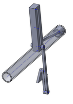
Thank you for your comment and the attached diagrams!
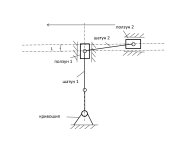
I imagine it roughly as it is shown in the attached diagram. The extension element is attached to the piston inside the combustion chamber.
I think that this is a solvable problem one way or another.
схема с камерой сгорания.png
 
Misclicked and gave a star to andrey; how do I take that back?
 
OK, now I understand. Your moving schematics are not showing the long fixed extension arm from the piston. This long arm is going to impose significant moment on the piston, increasing friction and the potential for jamming. Certainly, the piston length can be increased to work but then its mass increases. I will like to see your prototype.
 
Last edited:
OK, I understand, your schematic is not showing the long fixed extension arm from the piston. This long arm is going to impose significant moment on the piston, increasing friction and the potential for jamming. Certainly, the piston length can be increased to work but then its mass increases. I will like to see your prototype.
To create a prototype engine based on the proposed mechanism and perform a detailed analysis of its characteristics, it is necessary to involve specialists in this field, use special programs and technological equipment. This is the level of a specialized laboratory. I do not have such resources. I only have patents for this invention.
Therefore, the creation of a prototype engine and a detailed analysis of its operation are possible only if there is interest on the part of organizations that consider it appropriate to invest in the creation of a new engine based on the proposed mechanism. Or in using this mechanism in another capacity, which is still unknown to me.
 
The least any inventor could do is a mockup CAD model. Autodesk has a program aptly named "Inventor" you can use for free (non-commercially).

Even if the dimensions are not "correct" without detailed analysis, a 3D model would get people to understand and appreciate the concept more.
 
Consider contacting specialist laboratories with your proposal. They will want a full description with estimates and analyses for what your design is likely to accomplish with operational examples, and would very likely want a functioning kinematic model to show to those who would be paying to research your idea for you.

Since your design has dead-spots for both ends, it will need both a crank starter and something to initially push the piston to ensure it can get going. This will make it unsuitable for wind or wave generation drives.
 
If you try and include a cylinder block in your diagram you will see the problem is image_2024-11-13_084704804.pngaquatic mammals.
 
MintJulep, I agree. Andrey29R's answers have a repetition of phases and ideas that have me suspicious there is a script or some use of AI.
 
Last edited:
I use repeated definitions to ensure that the wording is correct and justified, and that there are no reasons to accuse me of providing false information and misleading people. In principle, everything is stated in the invention patent. The assumption about the possibilities of its use is based on my logical conclusions.
 
Ok - I get your reasons. Your proposed mechanism is interesting and I have found it engaging to understand what the benefits are and how it could be implemented. Good luck with your development work.
 
I wonder what you see as fraud here.
In most countries, patent law requires the holder to make a "reasonable" effort to develop the invention themselves. Patents exist to incentivize innovation. Filing them with no intention of developing an invention (ie for amusement, to immediately sell, or to block a competitor) is generally considered counterproductive to innovation - patent abuse/misuse. A reasonable effort can certainly fail, you can sell semi or fully developed IP at a later date, etc but governments dont want non-innovators abusing patent systems to monopolize/limit others' innovation. If a patent holder cant show reasonable effort being made then their patent can be invalidated by the courts, the same if its overly broad/vague like this one. Its typically a non-issue bc most put in quite a bit of work to analyze/test upfront before filing patents to ensure that patent costs can be recouped or are useful for marketing/otherwise. Usually the patent holder is the expert.
 
In most countries, patent law requires the holder to make a "reasonable" effort to develop the invention themselves. Patents exist to incentivize innovation. Filing them with no intention of developing an invention (ie for amusement, to immediately sell, or to block a competitor) is generally considered counterproductive to innovation - patent abuse/misuse. A reasonable effort can certainly fail, you can sell semi or fully developed IP at a later date, etc but governments dont want non-innovators abusing patent systems to monopolize/limit others' innovation. If a patent holder cant show reasonable effort being made then their patent can be invalidated by the courts, the same if its overly broad/vague like this one. Its typically a non-issue bc most put in quite a bit of work to analyze/test upfront before filing patents to ensure that patent costs can be recouped or are useful for marketing/otherwise. Usually the patent holder is the expert.
First you accused me of fraud, now you say that my patent is too vague. I received patents in different countries legally. It turns out that now you accuse the patent offices that issued me patents of negligence. I act strictly within the legal framework. I believe that my invention is useful for innovation, at least because it provides an opportunity to get acquainted with a mechanism that was previously unknown. And perhaps this will help optimize existing devices. High-quality patent development requires significant resources, first of all, specialists in this field with practical experience and specialized equipment. As for the courts with which you periodically threaten me, I do not force anyone to use my patent, I do not extort money and I do not mislead people. All information about my idea is set out in the patent for the invention, which I received in a completely legal way.
I am ending the dialogue with you, since it is not constructive.
 

Part and Inventory Search

Sponsor