Continue to Site

Eng-Tips is the largest engineering community on the Internet

Intelligent Work Forums for Engineering Professionals

  • Congratulations waross on being selected by the Eng-Tips community for having the most helpful posts in the forums last week. Way to Go!

Two-slider crank mechanism 8

To create faster and more economical internal combustion engines, I propose to use my invention - Riyanov double-slider crank mechanism (Two-slider crank mechanism). I received 4 patents in Russia (№ 2634851), China (№ 3349271), Japan (№ 6373516) and the UK (№ 3530879) for my invention, which can be used to create more environmentally friendly and faster engines, generators or in other projects.

SUBSTANCE: crank double-slider mechanism includes a crank, two connecting rods and two sliders. The second connecting rod is connected to the first slider at one end, and to the second slider at the other end. The second connecting rod length is equal to the sum of the double crank length and the distance between the connection point of the second connecting rod with the first slider in the initial phase of its movement measured in the direction of the first slider travel and the longitudinal axis of the second slider.
EFFECT: ensured full turn of the crank in one stroke of the extreme slider in the chain in one direction.

The unconditional effect of the two-slider crank mechanism is overcoming the limitation in the number of revolutions per minute in the internal combustion engine for the same working stroke of the slider, which can be used in internal combustion engines requiring high speed (for example, drones (land, air, water), subcompact cars, motorcycles), as well as in electric generators based on internal combustion engines, wave electric generators.

The key predicted effects are a gain in speed, a reduction in fuel consumption, the use of fuel with a lower octane number as a result of an increase in the working stroke of the slider, simplicity of design (gears are not used to double the speed).

I propose to use internal combustion engines based on the proposed mechanism primarily in unmanned aerial vehicles.

The subject of discussion is the possibility of practical application of the proposed mechanism in internal combustion engines.

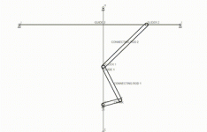
In existing internal combustion engines, the crankshaft makes half a revolution per stroke of the slider in one direction. In the proposed mechanism, it makes a full revolution per stroke of the outermost slider in the chain in one direction.Two-slider crank mechanism.jpgTwo-slider crank mechanism - animation.gif
 
Last edited:
For each combustion stroke in the original animation there is only one rotation of the crank.

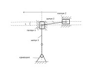
In the latest diagram it appears not to double the crank output but to cut the power output in half for each turn of the crank per combustion event.

If you have a pencil, some paper, and an eraser for tidiness, sketch a trimetric of the operation states of this engine.

This will show how the connecting rod is attached to the piston and how the piston is guided across the middle gap and how the connecting rod flips from one side of the piston to the other as shown in the original animation without interfering with the walls of the combustion chamber.
 
It isn't our job to convince ourselves this will work. It's yours to do the convincing. So far, number convinced is zero, both here and on the other forums you have posted this same idea. Your latest diagram is for a different linkage. Were I trying to sell this idea I would make a compressed air driven functioning model. At present there are functional alternatives with well established applications with far fewer parts, far less sliding friction, far less frontal area (critical for aircraft use) and far less critical stack ups of link lengths.

To overcome reluctance you need a functioning model and a power diagram showing how this linkage affects the thermal cycle.
 
Last edited:
You don't know why the stackup of link lengths is critical? I think you will when you make a model and it wedges tight and won't go over center.
 
It isn't our job to convince ourselves this will work. It's yours to do the convincing. So far, number convinced is zero, both here and on the other forums you have posted this same idea. Your latest diagram is for a different linkage. Were I trying to sell this idea I would make a compressed air driven functioning model. At present there are functional alternatives with well established applications with far fewer parts, far less sliding friction, far less frontal area (critical for aircraft use) and far less critical stack ups of link lengths.

To overcome reluctance you need a functioning model and a power diagram showing how this linkage affects the thermal cycle.
Thank you for your valuable comments! I am looking for people who are fluent in this subject and are willing to use my patents to create fuel-efficient and fast engines to meet people's needs and update their product line.
 
Anyway, cool animations.

What did you use to make them?
 
Anyway, cool animations.

What did you use to make them?
The kinematic diagram of the mechanism and its animation were created in the publicly available Linkage program. The recording of the mechanism's movement in video format was carried out using the OBS Studio program. The translation of this video into GIF format and its modification were done using one of the many online programs on the Internet.
 
You don't know why the stackup of link lengths is critical? I think you will when you make a model and it wedges tight and won't go over center.
I think that if there is sufficient play at the points where the links are connected, the mechanism will not jam.
 
Internal combustion engines operate for a few seconds with play in the linkage before they self-destruct.

It's your design, prove it won't jam by making one and demonstrating it.

Linkage is the product of Dave Rector a very interesting person who makes delightful marble track machines. He created Linkage to perfect the geometry of the ball lift sections of the machines and has some interesting discussions of the design decisions for the program.

I mention his name as it is far easier to find on-line than searching for Linkage would be.
 
Interesting mechanism. As 3DDave has mentioned a power diagram would be very telling to determine the potential usefulness of your design. I would really learn alot from seeing how that analysis is done. It appears to me the middle slider bearing will potentially empart significant power losses due to friction and/inertia, similarly the multiple links have inertial effects and multiple acceleration changes, and your main drive link from the piston is always at an angle greater than zero from the combustion chamber centerline so even at TDC the power stroke will deliver only a component of maximum force to the working links. Is your prediction of increased efficiency based on true analysis or just the schematic motion?
 
Linkage is a free computer-aided design program for Microsoft Windows used for prototyping of mechanical linkages.
 
The Linkage program provides the mechanical analysis? I will go check it out.
 
Linkage does graphics only. No analysis.

It's fun, but not a true engineering tool.
 
Interesting mechanism. As 3DDave has mentioned a power diagram would be very telling to determine the potential usefulness of your design. I would really learn alot from seeing how that analysis is done. It appears to me the middle slider bearing will potentially empart significant power losses due to friction and/inertia, similarly the multiple links have inertial effects and multiple acceleration changes, and your main drive link from the piston is always at an angle greater than zero from the combustion chamber centerline so even at TDC the power stroke will deliver only a component of maximum force to the working links. Is your prediction of increased efficiency based on true analysis or just the schematic motion?
A detailed analysis of the mechanism operation in relation to internal combustion engines was not carried out, since this is a task for a special laboratory due to many factors in action. The design can also be made in different versions. Friction in the mechanism links can be reduced using standard engineering solutions.

In my opinion, the acceleration of revolutions can be useful for unmanned aerial vehicles with piston internal combustion engines to increase their speed of movement when solving special problems. The engine can also be small in size for low-power drones.

If we do not take into account the speed factor, then in my opinion this design can be used for low-octane fuel, when there is no explosion in the combustion chamber, but a slower combustion. This can also be used in marine engines to save fuel.

Also, this design may be useful for power generators based on the energy of sea waves.
 
Linkage does graphics only. No analysis.

It's fun, but not a true engineering tool.
This program was used to create an animation of the mechanism. Analyzing the engine operation taking into account the non-standard design of the mechanism is a task for a scientific team. Perhaps a specialist with more experience can evaluate the potential of this mechanism to decide on further research.
 
Internal combustion engines operate for a few seconds with play in the linkage before they self-destruct.

It's your design, prove it won't jam by making one and demonstrating it.

Linkage is the product of Dave Rector a very interesting person who makes delightful marble track machines. He created Linkage to perfect the geometry of the ball lift sections of the machines and has some interesting discussions of the design decisions for the program.

I mention his name as it is far easier to find on-line than searching for Linkage would be.
Dave Rector's YouTube channel is worth a visit.
 
See https://blog.rectorsquid.com/ and https://blog.rectorsquid.com/art-projects/

Dave not only makes linkage animations, he produces working models among other works.
 
Granted I skimmed a bit, but I never saw any mention of how this is actually supposed to improve power outputs or fuel economy.

How exactly is increasing reciprocating mass and adding sliding friction losses supposed to gain you anything? Especially enough to offset the added cost and complexity that this new mechanism adds.

Just because you added a slider that operates in a different stroke-to-revolution ratio to the crank than your standard piston has, what does that ratio actually give you? Why is that important? Furthermore, even if that stroke-to-revolution ratio did mean something, your traditional piston is still there, you are just adding to it.

This could theoretically be a useful mechanism for converting rotational motion to linear-reciprocating, but should I need something like that it would be a stand alone device, not building it as part of an engine, and have to totally redesign everything we know about ICE's.
 
The effect of this mechanism is to achieve a full crank revolution in one stroke of the outermost slider in the chain (it is located horizontally in the diagram). This overcomes the limit of the speed of revolutions of a piston engine without gears.
As for fuel economy, the effect, in my opinion, is that less fuel is spent per crank revolution due to the fact that the crank makes a full revolution in one "burning". In addition, due to the lengthening of the slider path, I think that it is possible to use fuel with a lower combustion rate, which will have a beneficial effect on the environment.
Yes, you are right that power is lost due to a reduction in torque due to the reduction of the lever, so this mechanism can be used, among other things, in low-power engines, including electric power generators based on internal combustion engines and wave electric generators using the energy of sea waves.
Thank you for your opinion.
 
One full revolution of the crank shaft per stroke of the slider, I got that part, but again WHY do I care about this slider?

This overcomes the limit of the speed of revolutions of a piston engine without gears.

Engines that can rev very high have very LOW reciprocating mass. So again, why is ADDING mass with this slider going to help me spin the engine faster? Not just "because it will", give me some physics behind it. Gearing is irrelevant.

As for fuel economy, the effect, in my opinion, is that less fuel is spent per crank revolution due to the fact that the crank makes a full revolution in one "burning"

Suck - squeeze - bang - blow --> these are the 4 fundamental steps to the 4 stroke combustion engine. Your slider doesn't change any of that. For simplicity sake, you have 180deg of crank rotation for intake as the piston goes down, 180deg as it goes back up for compression, 180deg as it goes down during combustion, and 180deg as it goes up during exhausting. Your combustion period can only be for half a rotation, and that can only be every-other rotation. Adding and extra arm moving around up top doesn't change any of your valve timing. Aside from the fact that this will all be much more complicated as you now have to make room for these parts to accommodate your slider arm.

Also, there is a LOT of math that goes into balancing the pistons and the crank to each other to reduce/eliminate vibrations and moments. Your slider mass up top there is going to violently shake the engine back and forth.
 

Part and Inventory Search

Sponsor