Hi All
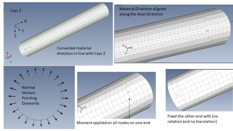
I am new to FEMAP, after using Abaqus and Ansys for many years. I am modelling a fibre reinforced composite cylinder, and applied Torque to one end of the model and fixed the other end, mimicking the a torsion test. I have listed my steps here in image below.

The in- plane shear modulus of the cylinder is coming out twice it is supposed to be. And even with a different layup it is much higher than it should be. I have taken the applied moment from the cross-section end subjected to torsion and found the shear stresses and used the rotation to determine shear strain (which all sounds right). I do not know where I am going wrong.
Can anyone advice ?
I am new to FEMAP, after using Abaqus and Ansys for many years. I am modelling a fibre reinforced composite cylinder, and applied Torque to one end of the model and fixed the other end, mimicking the a torsion test. I have listed my steps here in image below.

The in- plane shear modulus of the cylinder is coming out twice it is supposed to be. And even with a different layup it is much higher than it should be. I have taken the applied moment from the cross-section end subjected to torsion and found the shear stresses and used the rotation to determine shear strain (which all sounds right). I do not know where I am going wrong.
Can anyone advice ?
