Eng-Tips is the largest engineering community on the Internet

Intelligent Work Forums for Engineering Professionals

Approximating pressure on fan blade for static FEM

Status
Not open for further replies.

jt2001

Electrical
Apr 8, 2024
27
0
0
AU
Hello,

I have a fan hub I am looking to get an idea of the stresses it is under.

Is there a way of appoximating the force normal to the surface given:
- Air/medium density
- Radial velocity
- Fanblade geometery


Kind regards,

JT

Fan_gjnlgp.png
 
Replies continue below

Recommended for you

it depends on what you mean by "get an idea" ? how accurate ?

one thing to consider is that the angle of attack of the blade section changes with radial position (which is how large LP fan blades look so twisted). Your blade looks like a small HP blade, so this effect would be less.

An the load isn't likely to be "normal" to the blade surface ... local pressures are typically normal to the local surface, but the resultant will be skewed, probably forward of the blade reference plane.

"Hoffen wir mal, dass alles gut geht !"
General Paulus, Nov 1942, outside Stalingrad after the launch of Operation Uranus.
 
within 10% error/accuracy?

The blade is a cooling fan blade for a turbogenerator.

Is there literature you would recommend to estimate this?

Regards,

JT
 
Its not the data I am seaching for as much as the method to approximate it.

It is not so much for design but for awarness of failure modes in the machines I service.

 
Within 10% is difficult unless you have data from blade/fan manufacturer and which is difficult since proprietary information. With basic forces on fan blade using fluid mechanics theory/gross assumptions you can get some ballpark figures. Not sure about how much accuracy since not working in this field.

Some resources to look for-
Fan Handbook: Selection, Application, and Design
Fluid machinery books
 
"for awareness of failure modes in the machines I service." ... consult the manufacturer's manual and/or their service desk.

what concerns you ? Any loads in the servicing environment should be way lower than design loads.

"Hoffen wir mal, dass alles gut geht !"
General Paulus, Nov 1942, outside Stalingrad after the launch of Operation Uranus.
 
jt2001 said:
What propriatary data would I require from the OEM?

Not sure either. Maybe exact blade geometry or pressure varation along the blade or may be force you seek acting on the blade, I am not sure whether your modelled geometry is exact. But yes if you have access to data/personnel from fan manufacturer then you can save your time searching for answers.
 
you would need the aerodynamic pressure profile across the blade at different operating speeds. pressure will be a function of the airfoil shape, angle of the blade (akin to angle of attack of a wing), rotational speed, whether or not there is a outer shroud to reduce span wise flow, and a bunch of other things this non-aero engineer probably hasn't thought of. there are aircraft wing design text books that might help; don't know if there are similar for fan blades.
 
Might be out of my depth here.

Thought there might be a straighforward general formula using just the airfoil shape, angle of the blade, rotational speed.

I will have a search.

Regards,
 
if you're servicing these things, why concerned about design loads ?

If you're servicing these things, the manufacturer should be your first port of call. They know everything (or should do) about the fan.

Are you concerned you might damage the fan (when you service it) ?
The manufacturer should've provided suitable instructions about how to handle their equipment when servising.

"Hoffen wir mal, dass alles gut geht !"
General Paulus, Nov 1942, outside Stalingrad after the launch of Operation Uranus.
 
We do not service fans. But moreso the generator they are attached to.

I am looking to get an idea on where the stress concentrations might be. Given the aluminium fans on a particular rotor have undergone excessive corrosion.

As a result of this we are worried about potential cracking around the base of the vanes.

We would typically replace the fans outright on this basis however I am looking to give a bit more of an explanation as to why we would recommend to replace these.

It is a safe assumption that I will not be able to aquire the OEM instructions or specifications for this component. However they will be more than happy to supply a replacement part.

 
You have stress concentration in an irregular manner due to corrosion. That would seem to make for a difficult analysis.

In many situations like this is setting an inspection period, using dye penetrant inspection to find cracks and then polishing out the corrosion to remove crack initiation sources.

One could suppose that there is a 100% margin and so either replace the part when 30% of the material is removed if centrifugal loads predominate or 20% if bending loads predominate.

If there is a failure before completing an expected inspection period, check the results of the previous to compare to other examples. You may adjust the interval based on the remaining thickness.

Some destructive testing would use some bending cycles on a new fan; since the goal is to break blades you can vary the applied load for each blade on the fan and then repeat this sequence on a corroded fan to see what reduction results.
 
It is difficult. I would like to ask in general - is the centrifugal load the main source of stress in a part like this? (single part fan hub and blades as pictured).
How much of the total stress is due to the actual aerodynamic loads?
I would expect once the force due to lift is accounted for the maximum stress would spead accross the base of the blade of the bottom of the "wing" and the stress on the opposing side would lessen.

Pitting in question:
fan_pitting_fccztk.jpg
fan_pitting_2_t2bvti.jpg


My approach would be:
- Identify areas of significant corrosion pitting
- Compare the stress of the areas where pitting is found to the FEM model - and identify the corrosion sites most likely to compromise the part.
- Identify acceptable material removal without compromising mechanical strength of the part. Difficult as the aero-dynamic loads would appear complex to estimate to a reliable degree without complex CFD or OEM data - likely not within my capability.

Options for repair:
- As you say we could grind back the material to smooth any pitting - focusing on the areas of higher stress as these would be more vulnrable to propagation.
- Replace the fan blades entirely effectively removing all risk of failure due to the corrosion that has taken place. Which would be our prefered option due to obvious risk.

See below stresses from centrifugal force as computed in FEA. I note that I have not included (yet) consideration for the stresses due to the shrink fit on the rotor body.

Trailing_Edge_iuqjli.png

Leading_Edge_qidj1z.png
 
"more of an explanation as to why we would recommend to replace these."

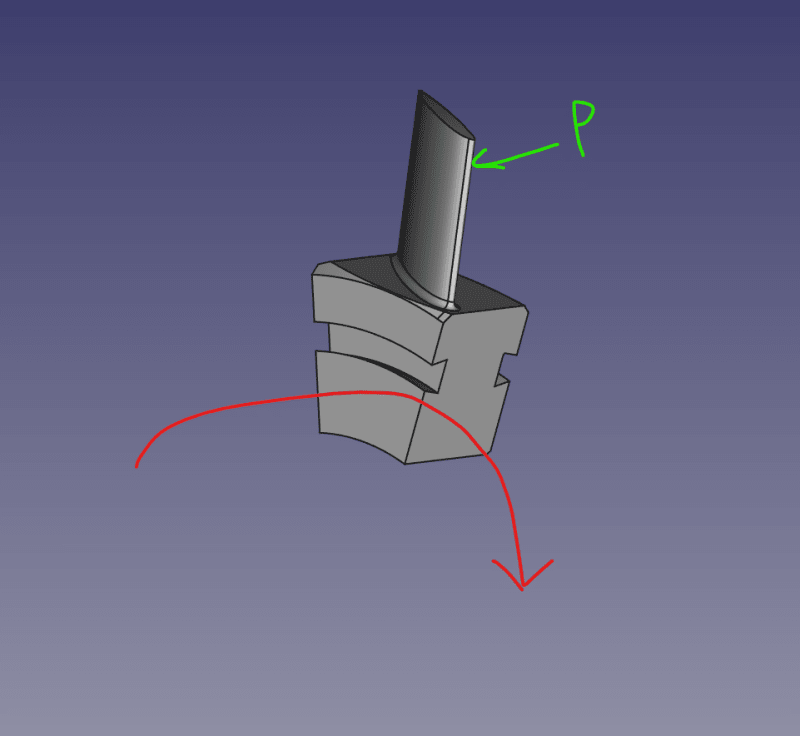
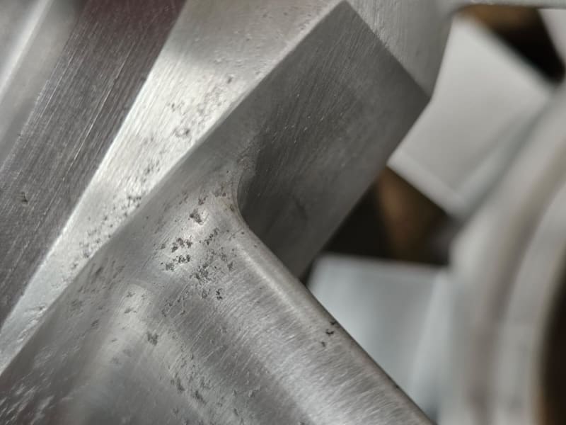
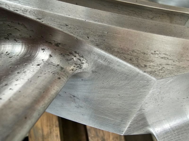
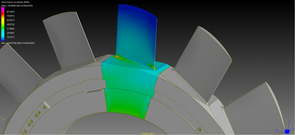
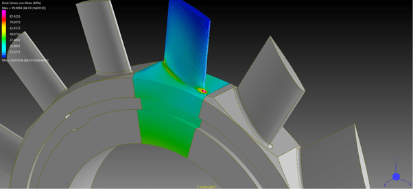
1) service experience ! "Given the aluminium fans on a particular rotor have undergone excessive corrosion."

but I don't understand where you ae in this problem.

you say you are not the manufacturer, ok?

but I assume you are also not a customer (otherwise you'd have access the the maintenance manuals, etc ... and maybe some warranty ?

so are you a competitor ?

ok, so these units undergo "severe" corrosion ...
does every unit, or a very large proportion ... which would point to a design problem,
or is it a specific customer, a geographic area, a group closely matched in time ... which would point to a more specific problem ?

but, ok, the fan undergoes corrosion. I'm sure there are standard things that can be done to mitigate corrosion.

"Hoffen wir mal, dass alles gut geht !"
General Paulus, Nov 1942, outside Stalingrad after the launch of Operation Uranus.
 
what mass is the blade? what rpm? how far is it from the shaft? F=m*r*w^2 as you learned in school
aero force is perhaps 1/2*1.1*A*1.2*(w*r)^2 where A is blade width * height, applied 70% up the blade. M/I=sigma/y as you were taught at uni.

so now you can compare bending stresses at the root compared with centrifugal force at the root, and throw your silly colored diagrams away.


Cheers

Greg Locock


New here? Try reading these, they might help FAQ731-376
 
Thankyou Greg,

That is what I am looking for. Determining the co-efficient of lift from the vane geometry is where I come unstuck,

I do like my colored diagrams ...

Cheers
 
By any chance do you know the power draw of this component? If so, you might apply a pressure gradient that follows the function R^2 and has a total magnitude meeting the power draw.

The pressure distribution itself does not need to be perfect, as we already know the stress-limiting locations. You just need to apply an appropriate bending load to the blade.

Getting the drag data will be much harder than the stress analysis you ultimately want to perform, but if you believe the drag is high, you can skip the R^2 and apply a point load at 3/4 of the blade radius and increase/angle the point load vector to include some drag.

You're not going to get any closer to reality than that unless you have a very high end CFD package and appropriate test data to tune the CFD model.
 
Status
Not open for further replies.
Back
Top