Eng-Tips is the largest engineering community on the Internet

Intelligent Work Forums for Engineering Professionals

Approximating the forces on a beam for recovery towing operation

Status
Not open for further replies.

MechEng0001

Mechanical
Jul 29, 2024
4
0
0
AU
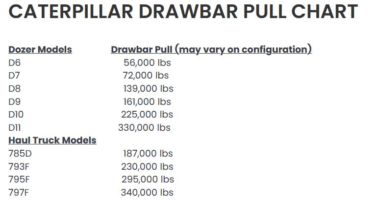
We have a large 200 tonne catamaran-style dredge that we are planning to tow with a couple of D11 dozers up a hill. We are designing a platform that it will sit on and be lashed down to, and this is what the dozers will be attached to using towing strops. This platform will have a large welded beam across the front of it, however, I need to establish the how the loads are being applied to it so we can size the beam in our beam calculators.

Picture2_ltnokd.png


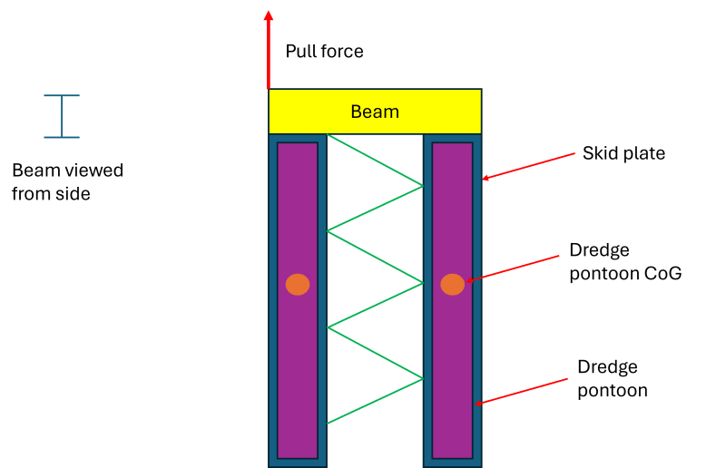
In the attached sketch, we have assumed that the dozers may stop and start, so the entire force from one may be applied to a single side at any one time. We have also assumed that the structure of the dredge cannot/will not take any of the load through it. We have assumed this because we don't know if the structure is strong enough to handle these loads. So, essentially we have two pontoons acting independently. I figured we could assume a point load where the centre of mass is in these pontoons, which is essentially the reaction forces. However, this could also be a distributed mass as the skid plate will be connected along two lengths of the beam, I'm not 100% sure. If point loading is a worst case scenario and makes the calcs simpler, we are happy to assume that. The link below is an Excel file showing how I calculated the reaction forces from the moments.

Beam Calcs

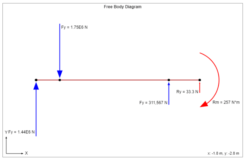
Now, technically the beam will move when the required force is applied. This is problematic for beam calculators as it's not constrained. I have done a force balance calculation to find the reaction forces from the location of the pontoon CoGs and modelled these as forces. There is some residual force/moment at the end of the beam, which was required to be added into the model as a fixed joint to constrain everything, however this is negligible.

Capture_rpwcu3.png


So me question is, is this the correct way to set up this beam analysis? Are my assumptions reasonable? Something just feels off about it and it doesn't fill me with confidence. Any input would be appreciated.
 
Replies continue below

Recommended for you

Why not pull from the center of the beam? And possibly add an equalizing chain to the link point from the two D11s so the beam always sees tension from one point, with a slightly varying angle if the movers start/stop independently? then you only need to reinforce the link point.

As shown, this looks like a great way to try and rip the beam off the skid plates, or get the entire thing cocked sideways and introduce shear load on the dredge platform where it connects to the pontoons.
 
Orange_kun said:
Why not pull from the center of the beam? Or add an equalizing link to the two D11s

It needs two dozers to pull it out, one isn't enough. We can't use wire rope, site standards, strops are all we can use. The rigging plan for this is already done and not our area, our job is to build the platform.
 
Sounds interesting - is the skid dragging on ground, wheeled, rolling on air-logs, floating, etc? i.e., do you know your towing forces? Not planning on opening the excel file. Also, not quick enough to understand how the fbd relates to your sketch. What happens if the load abruptly stops?

drawbar_i08pxv.jpg
 
dvd said:
Sounds interesting - is the skid dragging on ground, wheeled, rolling on air-logs, floating, etc? i.e., do you know your towing forces? Not planning on opening the excel file. Also, not quick enough to understand how the fbd relates to your sketch. What happens if the load abruptly stops?

The skid is dragging on the ground. All load calcs have been done for that. Please ignore how the load is being applied and rigged up, it's already all decided and signed off by a team of site engineers, so we have no say on that. Our area now is the skid with the given loads.
 
GregLocock said:
What Factor of Safety do your insurers/legislation require for towed loads like this? Your assumed load seems very low (~1g), given that you are dragging this thing uphill over (I assume) rough ground and impacts will occur. What is the purple bracing?

The safety factors all come from mine standards. The load is the max drawbar pull for a single D11T in first gear pulling at a specific angle with a specific grade of road and includes dynamic loading while accelerating. Safety factors will come in at the end. However, I'm conscious about getting sidetracked on the rigging and towing aspect here as our focus is currently on how to model the beam with the current loads that we have been given.

The bracing is to keep the two skids apart while turning.

Cheers
 
I don't understand how you can begin to model the beam loads without being clear on how the rigging attaches to the beam. Your diagram shows the pull force at the extreme left end of the beam. Is that where it is, or is it centered/distributed? Are we assuming the pull force is applied parallel and in plane with the beam web? Is the beam welded on only one side of the flanges?

The bracing matters as well. After all, it's going to prevent the skids from coming together and bending the beam further.

I don't see reason to do a beam bending calc without more info. There's so much missing from the picture. As far as I can tell, they want to drag it on an angle as shown.

Since the beam is unconstrained, you need to change the angle of the beam until the friction forces at each pontoon COG are equal distance on either side of the pull point. Then you can solve for the actual moments and forces within the beam by resolving the angled pull and friction forces into x and y components for the calculators.
 
It is understandable that you want to get the answer to your question and not talk politics, or sports, or the weather. Good luck. Who owns the responsibility if the outcome is not as desired - the beam designer or the site engineers? It seems unrealistic to think that this is a simple beam. What does a padeye for a 200 tonne load look like? Are you going to weld that to the beam flange? (200 ton shackle dims)

As another aside, since this is a mine, how strong of belting do you have? Consider putting the dredge on (ST 10000 or something very strong) belting with appropriate pulling (I could elaborate on that) and drag it.
 
Hi MechEng0001

I am trying to follow your calculations and I assume the 1.3m and the 7.5m are the horizontal distance between the two skid centrelines?
Also what the incline of the slope you are dragging this thing up and the coefficient of friction?
What is the distance between the reaction forces and the applied pulling force shown on your free body diagram?
I don’t believe your approach is correct but there is a lot of information not given.
I would be more concerned about the size and strength of the weld that you are using to attach the beam to the skids.

“Do not worry about your problems with mathematics, I assure you mine are far greater.” Albert Einstein
 
I'm struggling here to understand the free body diagram and also what exactly is connected to what and how?

Is the view of beam from the side correct? Maybe a side view would help clear this up.

"as the skid plate will be connected along two lengths of the beam," Eh??

SO are the pontoons connected via a flexible central anchoring point or welded to the beam or what?

I suspect the answer is going to be don't pull with only one dozer.

Remember - More details = better answers
Also: If you get a response it's polite to respond to it.
 
Generally when engineers try to do too much arithmetic vs simply using modern CAD and FEA tools they make simple but catastrophic mistakes bc they overlook important details.

Your beam size (and whether/not you even need the beam) will depend on the stiffness of the pontoon structure and the unevenness of the ground. Typically you'd start the design by sizing the skids for an acceptable ground pressure while operating on max slope, and design the tow points last. Point loads on the skids are your biggest enemy, both the skids and entire structure need to be flexible enough to prevent damage. When you finally get to designing the tow points you need to keep in mind that they will see both bending and torsional effects simultaneously.
 
Status
Not open for further replies.
Back
Top