Continue to Site

Eng-Tips is the largest engineering community on the Internet

Intelligent Work Forums for Engineering Professionals

  • Congratulations KootK on being selected by the Eng-Tips community for having the most helpful posts in the forums last week. Way to Go!

Are these equivalent? 1

gb2835

Mechanical
Aug 24, 2021
34
See attached.

I understand that with the left FCF that Rule 1 no longer applies. The right FCF, though a different symbol, controls the same thing (form of axis). Would Rule 1 also not apply with the TP? This came up on a drawing I reviewed. I told the designer to switch the TP to Straightness since that was really their intention. I personally don't use TP without datums, so perhaps others have a better handle on this. It did get my head scratching though, let me know what you think!
 

Attachments

  • Figure.png
    Figure.png
    7.1 KB · Views: 19
Solution
Position controls the location and orientation of the axis of the unrelated actual mating envelope. Without any references and not being part of a pattern, there is no control on the location or orientation of the axis of the unrelated actual mating envelope.

Position doesn't control the form of a feature, so they are not equivalent.
Replies continue below

Recommended for you

1732997220783.png
It's tough to say if it is equivalent as the position tolerance in this case is nonsense. Dropping the FCF entirely would control the straightness at MMC by the envelope principle for ASME Y14.5. Neither one applies a tighter tolerance than the size tolerance so the straightness tolerance isn't helping.
 
My thoughts are there is no stated tolerance on straightness so rule #1 is basically still in place. They are doing the same thing with form but obviously straightness doesn't care about location

Straigtness also cares about derived median line coming from many midpoints created from opposite points from the surface. It is more of a surface check than position which is just checking some fake axis line in space that doesn't exist. I deal with some of the craziest non feature of size position checks you could imagine and trying to find the fake axis on a 25deg arc radial cutout is fun when no one agrees with each other. I now measure these features behind the scenes with surface profile bc that is what the mating part cares about.

Since you have MMC on the position there is a virtual surface condition boundary that in essence kindof functions as surface profile if you hard gauged it. But using something like a CMM could still violate the surface condition bc not all hits will fully encompass the entire part/feature. That said since the MMC position basically shouts that the surface shouldn't break the virtual condition boundary it would be more proper that the form check of straightness have a smaller tolerance than is stated. Since it is zero you can't do that so the straightness tolerance is taken care of with the position check. So given the MMC callout on both they check form similarly, in my opinion.
 
Thanks 3DDave and sendithard, I think you both have collectively reminded me of something.

To be fair, I put the .000 tol as a default. The actual drawing had something like .010 tol. But yes without the FCFs in the figure I provided the envelope / median line principle accomplishes the same thing. Adding a nonzero tol would then have to negate the principle in order to make sense (perfect (zero) form no longer needed at MMC). My goal was more to reinforce the idea that a TP of an axis without datums is equivalent to Straightness applied to the circular FOS.

And to sendithard, I've 100% been there on finding the median line/curve of a non FOS and 5 different people have 10 different opinions [upsidedown]
 
Position controls the location and orientation of the axis of the unrelated actual mating envelope. Without any references and not being part of a pattern, there is no control on the location or orientation of the axis of the unrelated actual mating envelope.

Position doesn't control the form of a feature, so they are not equivalent.
 
Solution
3DDave, let me probe this a bit further to clarify something that I may have been mislead on in the past.

I've seen a lot of TP being used to just define orientation, not location. For example, a TP on a hole referenced to datum [A] which is a flat surface. Nothing special here, just a single hole in a plate. This was taught to me as the equivalent as swapping the TP for Perpendicularity.

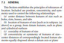
What you're saying makes more sense, because I always thought "why not just use Perpendicularity then?" Looking at the attached, I also don't see orientation only listed (Section 7 Tolerance of Location, 2009).

Would you mind briefly speaking to this? My own fault for not digging into this more myself.

1733001147198.png
 
Orientation control is an unavoidable side effect of the position tolerance zone.

This is buried in the Appendix item B.5, ASME Y14.5-2009. The formula there can only be derived by acknowledging the allowable orientation variation allowed by a position tolerance.

It is depicted in such as Fig. 7-8

"This was taught to me as the equivalent as swapping the TP for Perpendicularity." is incorrect teaching.

I feel like that use should be allowed, but the authoritarians who wrote the standard and those who support the authoritarians say it is never allowed. If the authoritarians feel that strongly they should plainly state it, knowing this has been a point of pain for a number of users. It does however allow those who write the standard to include this withheld information in their very costly courses and books.
 
3DDave, let me probe this a bit further to clarify something that I may have been mislead on in the past.

I've seen a lot of TP being used to just define orientation, not location. For example, a TP on a hole referenced to datum [A] which is a flat surface. Nothing special here, just a single hole in a plate. This was taught to me as the equivalent as swapping the TP for Perpendicularity.

What you're saying makes more sense, because I always thought "why not just use Perpendicularity then?" Looking at the attached, I also don't see orientation only listed (Section 7 Tolerance of Location, 2009).

Would you mind briefly speaking to this? My own fault for not digging into this more myself.

View attachment 1764
The misinterpretation that position can be used as an equivalent way to state perpendicularity probably results from overseeing the difference between applying it to a single feature and to a pattern. When a pattern of holes is positioned relative to planar datum feature to which it is perpendicular, the requirement is not only orientation, but also mutual location within the pattern, as the tolerance zones are fixed together (in addition to being perpendicular to the datum). With perpendicularity, this couldn't be achieved. This is what makes it useful for a pattern, and meaningless for a single hole.
 
  • Like
Reactions: ewh

Part and Inventory Search

Sponsor