Eng-Tips is the largest engineering community on the Internet

Intelligent Work Forums for Engineering Professionals

AS 3600 AMDT 2 Equation 8.2.7(2) additional longitudinal tension forces caused by shear 2

Status
Not open for further replies.

kww2008

Structural
Feb 1, 2008
149
0
0
AU
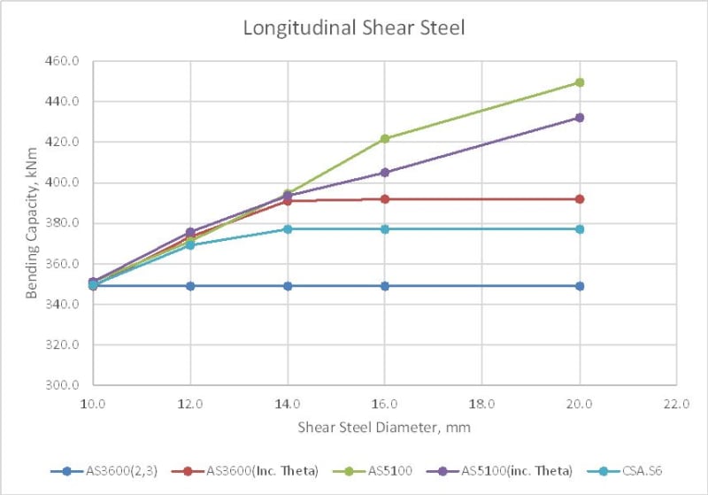
I have recently had a look at this amendment. This is now different from the same equation in AS 5100.5 as phiV_us has been replaced by (V* - phiV_uc), and "gamma_p P_v" by "0.5 gamma_p P_v". This equation is also different from those of AASHTO and the Canadian code. Does anyone know the reasons for these changes?

A potential problem arises if adopt this equation in AS5100.5, and use it for load rating to AS 5100.7.
When using (V* - phiV_uc) instead of phiV_us, there is an implicit assumption that the ligaments (stirrups) provided is such that phiV_us + phiV_uc > V*, which is okay for designing bridges. Section-shear deficient bridges have [phiV_us + phiV_uc] < V*, i.e., [V*-phiV_uc] > phiV_us. If we use the AS 3600 equation to load rate force in the longitudinal steel, this introduces inaccuracy as the amount of force deducted (V* - phiV_uc) is larger than phiV_us. The canadian code has a limit "V_s not to be taken great than V_u" for their equation which uses V_s.


Replies continue below

Recommended for you

The old equation was being misused in practice by adding large areas of vertical reinforcement to reduce the longitudinal requirement to 0, based on the assumption that phi Vus is the capacity of the vertical reinforcement. That is not actually correct. Vus is the excess of Applied Shear above the Concrete Shear capacity.

The modified requirement simply uses the logic that Vus = V* - phi Vuc substituted in the old equation, which is what the old clause actually required but was mis-interpreted.

The current rule still limits the total of .5(V* + Vuc) to V* in the last sentence, so if Vuc is excessive, then the extra is ignored.

Hopefully AS5100 will fix this problem in future as it was actually some bridge designers who were found to be misusing it.
 
The equations in AS 5100.5 must be suitable for both bridge design to AS 5100.5 and bridge asseessment (load rating) to AS 5100.7. The latest equation 8.2.7(2) in AS 3600,when using (V*-phiV_us), as stated in my earlier comments, assumed that [(phiV_us + phiV_uc) >= V*] which is not suitable for load rating.

For a section-shear deficient bridge at the most critical loading, [(phiV_us + phiV_uc) < V*], i.e., [phiV_us < (V*-phi V_uc)], and therefore if we use use (V*-phiV_uc) in place of phiV_us, we incorrectly assumes that the amount of ligatures provided is more than the amount in the bridge.

Also, it appears that using the equation in AS 3600 AMDT 2 is too restrictive regarding the ability to decrease longitudinal steel by using increasing ligatures as the canadian standard uses V_s (equivalent to our phiV_us) not to be greater than V_f (equivalent to our V*). If previous bridge designers were putting in too much ligatures, it is because the condition "phiV_us not greater than V*" is not in AS 5100.5. This should be fixed.
 
The final note to Cl. 8.2.4.2.2 (and 8.2.4.2.3) allows the strain value to be increased above the value given by the equations in the clause (up to a maximum of 0.003), which will increase kv (and reduce phiV_uc) and increase theta, which will reduce cot(theta). This will allow a limited reduction in the longitudinal force if additional vertical shear reinforcement is provided to maintain the required total shear capacity.

Some quick calculations suggest that the limit on the reduction is similar to the limit in the Canadian code.

Doug Jenkins
Interactive Design Services
 
I think we assume that engineers are intelligent human beings.

- If there is insufficient ligatures supplied, then one would think they would base the load rating calculation on what is supplied, not what is required.

- If you put in 5 times as many ligatures as is required for Vus, then those ligatures will not be at yield. They cannot create force! You will not get 5 times as much Vus. As IDS suggested you can recalculate the shear capacities to account for the actual reinforcement supplied up to a point.

It is important in all of these calculations for load rating that Equilibrium, Strain Compatibility and Statics be satisfied at the inclined crack.
 
To compare the different code requirements, and the different approaches to applying them, I have looked at the bending capacity of a rectangular beam, including shear effects, when the shear reinforcement is increased from 10 mm up to 20 mm. The beam had a bending capacity of 446 kNm with zero shear, and a shear capacity of 275 kN with 10 mm shear reinforcement at 200 mm spacing. I checked the bending capacity including shear effects with a V* of 275 kN, for the following cases:

1) AS3600, rev 2 or 3, with the shear inclination angle (Theta) according to the code refined method.
2) As above but with Theta increased to reduce the shear capacity to 275 kN, up to a maximum of 50 degrees (equivalent to the maximum mid-height strain of 0.003).
3) & 4) As 1) and 2), but to AS5100 rev 1.
5) As 3) but with Phi.Vus limited to V*, as required by the Canadian Code.

LongShear1-1_b8b6ig.jpg


In summary:
Case 1) Increasing the shear reinforcement has no effect on the bending capacity.
Case 2) Bending capacity close to the AS5100 results, until the limit on Theta of 50 degrees is reached, then constant. Note that this is fully compliant with the current AS 3600.
Case 3) Increasing the shear reinforcement area continues to increase the bending capacity, to an unrealistic degree.
Case 4) Some reduction in bending capacity, compared with 3), for 16 and 20 mm steel, but still much higher than 2).
Case 5) Similar results to 2) to 4) for 10 and 12 mm, but the limit on Phi.Vus is more conservative than the AS 3600 limit, at least in this case.

On that basis I'd suggest that the current AS3600 method, with adjusted Theta, has reasonable limits, without being too conservative.

Doug Jenkins
Interactive Design Services
 
Doug,

Could you please describe the steps in your calculation for Case 3 which resulted in an increase in bending capacity from an increase in the area of shear reinforcement ?
 
C
kww2008 said:
ould you please describe the steps in your calculation for Case 3 which resulted in an increase in bending capacity from an increase in the area of shear reinforcement ?

I have just posted a more detailed description of the analysis (together with a link to the spreadsheet used for the analysis at:

But in brief:
Case 3 is just using the AS5100.5 code formula for the longitudinal force due to shear, and finding the adjusted bending capacity, allowing for the force. Increasing the shear reinforcement reduces the longitudinal force, so increases the bending capacity.

For Case 2 increasing the compression block angle (Thetav) reduces the concrete shear force, and also reduces the cot(Thetav) factor on the longitudinal force, so it increases the adjusted bending capacity, up to the limit of Thetav = 50 degrees, equivalent to a mid-depth strain of 0.003.


Doug Jenkins
Interactive Design Services
 
rscassar said:
do u think the variability across codes is a bit concerning?

I think the uniformity across codes when there is a reasonable limit on the Vus value is quite encouraging :)

But yes, the AS 5100.5 results with no limit on Vus is a bit of a worry, which is why the equation was changed in AS 3600.


Doug Jenkins
Interactive Design Services
 
I would hope that designers appreciate all of the things we improved a lot in shear and development.

- The old AS3600 longitudinal tension reinforcement requirements were completely impossible to apply. RAPT had not used them for about 15 years, using a slightly different version of the current rules adopted from Eurocode until we finally got the rules sorted out in AS3600-2018.

- Yes, Vus should have been limited. But that was initially transferred from AS5100 which had been checked and approved and in use for a couple of years. Because of that we had an even harder fight to get it changed as it was already accepted so we were putting out a code different to the new AS5100. We were working on the unfounded assumption that engineers would use Vus = V* - phi Vuc. Unfortunately that is not the definition in the code (ironically it is the definition in RAPT as a design program).

If you look back through Mitchell and Collins work, the actual formula has Vuc + .5Vus, which they then modified to the current Canadian rule by substituting for Vuc using the same equation we did eventually, Vus = V* - Vuc, except that they removed Vuc and left Vus in the formula. This caused all of the problems with Vus. We changed it to remove Vus and have Vuc in the formula with an upper value on Vuc of V*, so the total maximum is V* when Vuc >= V*. Which is pretty logical as the total reaction from the shear cannot be greater then the shear itself! As I said previously, a much larger area of vertical reinforcement will be at a lower stress to give the same vertical shear capacity. It will no longer be at yield which designers were assuming. Unless you used Prestressed shear reinforcement, you cannot generate more vertical force just by adding more steel! So Vus could never be as high as it was assumed by some.

- the other major one we fixed as Prestress being treated as part of the capacity and multiplying it by Phi. This is still wrong in most codes that use overall capacity factors. In a situation where the pretstress increases the applied shear, the code has always allowed the designer to reduce that increase by about 30% by multiplying it by phi. Completely illogical. It should be increasing it, which is now what happens with the Partial Factor we have introduced. Unless that has changed recently it is still wrong in AS5100, in members that tend to have very high levels of prestress where it will have more effect, especially at transfer in heavily stressed pretensioned members or simply supported members or with load reversals from moving loads!
That one will really stuff up anyone doing load ratings on bridges in future!

- Which is another thing we fixed as many designers never checked shear at transfer. At least we now tell them to.
 
Quoted IDS "Increasing the shear reinforcement reduces the longitudinal force, so increases the bending capacity"

Doug,

For given V*,M*, A[sub]st[/sub](provided),A[sub]sv[/sub](provided) and s, where M* < Φ M[sub]u[/sub] and V*<Φ(V[sub]us[/sub]+V[sub]cs[/sub]), increasing the amount of shear reinforcment A_sv(provided) increases the shear capacity ΦV[sub]u[/sub] [= Φ(V[sub]us[/sub]+V[sub]cs[/sub])] but not the moment capacity ΦM[sub]u[/sub]. Is there an assumption I am not aware of?
 
kww2008 - I am looking at the bending capacity under combined bending and shear, including the longitudinal force due to shear. Increasing the area of shear reinforcement allows the angle Theta to be increased (up to 50 degrees)[pre][/pre], which reduces the longitudinal force due to shear, so increases the force available for bending.

See the link in my earlier post for more detail.

Doug Jenkins
Interactive Design Services
 
The term for prestressing γ[sub]p[/sub]P[sub]v[/sub] in Equation 8.2.7(2) AS 5100.5 is correct and the term 0.5γ[sub]p[/sub]P[sub]v[/sub] in Equation 8.2.7(2) AS 3600 is not. The equation in AS 5100.5 can be derived using a free body diagram (see attachment), as described in Commentary C5.8.3.5 of AASHTO LFRD Bridge Specification, 5th Edition.

The equation in AS 5100.5 should not be changed to that of AS 3600 as ØV[sub]us[/sub] in the equation is the capacity of the the shear reinforcement provided, which is correct. Replacing this with (V*-ØV_[sub]c[/sub]) is not strictly correct as (V*-ØV_[sub]c[/sub]) is the ØV[sub]us[/sub] required to satisfy ØV[sub]u[/sub] = V*. It is therefore not the ØV[sub]us[/sub] of the reinforcement provided, which is usually larger. Using the equation in AS 3600 is overtly restrictive, as any excess reinforcement we provide above the amount required for shear adequacy is not considered when calculating the amount of longitudinal steel.


The identified problem with AS 5100.7 not restricting the amount of shear reinforcement provided should be rectified by adding a requirement "ØV[sub]us[/sub] shall not be greater than V*". This requirement is in agreement with that provided in the Canadian Standard which states that "V[sub]s[/sub] shall not be greater than V[sub]f[/sub]", Also in agreement with that provided in AASHTO LRFD Bridge Specification, 5th Edition, where in Clause 5.8.3.5, it states that "V_[sub]s[/sub] not be taken as greater than V[sub]u[/sub]/Ø". This requirement gives a reasonable upper limit since the amount of shear reinforcement that can be used cannot exceed that required to resist the design shear, assuming ØV[sub]uc[/sub] =0 (i.e,concrete not resisting shear).

 
 https://files.engineering.com/getfile.aspx?folder=7f2b295a-91f7-46c3-94bb-799fea313126&file=Delta_F_td.png
My previous posts dealt with sections with passive reinforcement only, so I'll respond to that point first.

Using ØVus as the force in the vertical reinforcement is only correct if the reinforcement can actually develop that force. As the example posted previously shows it may be highly unconservative. The equation in the current AS 3600 in conjunction with adjustment of the compression strut angle gives the same results, but with a restriction on the shear steel area based on the actual shear failure mechanisms. The alternative of using the minimum calculated strut angle will be conservative (assuming that the shear reinforcement area is adequate for vertical forces), but if the area of shear reinforcement is being increased to satisfy longitudinal force requirements it doesn't take a lot of extra work to adjust the strut angle.

The current AS 3600 requirements are therefore logical and need not be over-conservative and I see no need to change them. AS 5100.5 may be highly unconservative and does need to be changed. It would make sense to change it to be the same as AS 3600.

Regarding the vertical prestress force, the point is not whether the equation satisfies equilibrium, the problem is if the force is increasing the applied shear force it shouldn't have a capacity reduction factor applied to it. In the current AS 5100.5 Pv is defined as part of the section capacity in Cl. 8.2.3.1, but this refers back to Cl. 8.2.1.2 (which should be 8.2.1.3), which deals with Pv being greater than V*min. In this case Pv is treated as being an applied load, and is factored up, and is now (Amendment 1) removed from the capacity equations. Note that Cl 8.2.7 (longitudinal forces due to shear and torsion) now has a gammap factor which varies according to whether PV increases or reduces shear. This seems inconsistent with 8.2.1.3.

In the current AS 3600 Pv is always treated as part of the applied load (8.2.3.1) and is factored down or up depending on whether it reduces or increases the design shear force. This seems a simpler and more logical approach to me.

Doug Jenkins
Interactive Design Services
 
The equation 8.2.7(2) in AS 5100.5 is similar to those provided in AASHTO Bridge Specification and the Canadian Standards for force in longitudinal reinforcement from combined action effects. The Canadian and American started using MCFT in the 1990s. I wonder if they have concern on the use of these equations.

When using the free body diagram to derive the equation, an assumption is made that the collapse mechanism occurs when all the reinforcement provided (assumed to be fully anchored) have yielded after reaching the loading level for M* and V*.


kww2008 said:
The equation 8.2.7(2) in AS 5100.5 is similar to those provided in AASHTO Bridge Specification and the Canadian Standards for force in longitudinal reinforcement from combined action effects. The Canadian and American started using MCFT in the 1990s. I wonder if they have concern on the use of these equations.

But the Canadian codes and AASHTO limit Vs to be no more than Vu and AS 5100.5 doesn't.


kww2008 said:
When using the free body diagram to derive the equation, an assumption is made that the collapse mechanism occurs when all the reinforcement provided (assumed to be fully anchored) have yielded after reaching the loading level for M* and V*.

Which is why it is reasonable to increase the strut angle (up to a limit of 50 degrees) so that the shear steel can reach yield, which reduces the calculated longitudinal force.

Doug Jenkins
Interactive Design Services
 
3 things

- to have equilibrium in the free body diagram, Vu* = Vuc + Vs. If V* = Vus in that diagram shown above, you do not have equilibrium!

- I know those codes allow it, but using Vs = V* means you are assuming Vuc = 0.

All of the testing and development of the MCFT says Vuc does not go to 0.

- as I said earlier, in the original MFCT development by Collins and Mitchell, the formula for longitudinal tension force was based on Vuc + Vus. V* did not appear.

The equality Vus = V* - Vuc was used to convert it to a formula based on V* and Vus.

But that conversion relied on that equation. You cannot then reset the factors in that equation to a different reality after you have used the logic to develop it.!

Now that the conversion has been done, you then set Vuc to 0.

You cannot have it both ways.

Maybe some other codes should be questioned rather than AS3600!

 
Kww2008,

Am I reading your equilibrium results correctly and you are getting longitudinal tension from shear in the bottom and longitudinal compression in the top?

Everyone else gets tension top and bottom as longitudinal forces from shear.

There appear to be a few loads missing or ignored in your equilibrium. We developed it all from 1st principles as C&M gave a very abbreviated listing of their math with some significant jumps in logic and we wanted to confirm how they got there.
 
RAPT,

You are correct about the top force from shear is not compression. That is a mistake in my diagram. The diagram is similar to the one use in AASHTO Bridge Specifications, and AASHTO does not has a top longitudinal force in steel in their diagram since their standard does not require this force to be calculated. I added the the force ΔF[sub]cd[/sub] which is not correct.

 
Status
Not open for further replies.
Back
Top