Continue to Site

Eng-Tips is the largest engineering community on the Internet

Intelligent Work Forums for Engineering Professionals

  • Congratulations KootK on being selected by the Eng-Tips community for having the most helpful posts in the forums last week. Way to Go!

AS 3600 AMDT 2 Equation 8.2.7(2) -continuing a previous thread

Status
Not open for further replies.

kww2008

Structural
Feb 1, 2008
149
The thread744-499791 is closed. To continue discussing, I created this new thread.

In a former posting by Doug (IDS(Civil/Environmental)in the thread, he stated:

"Case 3 is just using the AS5100.5 code formula for the longitudinal force due to shear, and finding the adjusted bending capacity, allowing for the force. Increasing the shear reinforcement reduces the longitudinal force, so increases the bending capacity."
as a response to my query:
"Could you please describe the steps in your calculation for Case 3 which resulted in an increase in bending capacity from an increase in the area of shear reinforcement ?"

My understanding of the analysis described in Doug's blog (link provided in thread744-499791) is as below.

The total longitudinal steel A[sub]st1[/sub] is first determined for shear reinforcement A[sub]sv1[/sub]/s for a section with design shear V*[sub]1[/sub], ultimate shear strength V[sub]u1[/sub] such that the axial force in A[sub]st1[/sub] is close to f[sub]sy[/sub] under combined action effects M*[sub]1[/sub] and V*[sub]1[/sub]. The shear reinforcement is the increased to A_[sub]sv2[/sub]/s with the following values kept the same:
V[sub]u2[/sub] = V[sub]u1[/sub],
V*[sub]2[/sub] = V*[sub]1[/sub]
A[sub]st2[/sub] = A[sub]st1[/sub]
A new moment effect M*[sub]2[/sub] is then determined through trial and error (or iteration) so that A[sub]st2[/sub] is close to f[sub]sy[/sub].
Owing to M*[sub]2[/sub] determined being greater than M*[sub]1[/sub], it was concluded that an increase in the shear reinforcement caused an increase in "reduced moment capacity"

Doug,
Before I discuss further, I would like to check whether my description of the analysis above is accurate.
 
Replies continue below

Recommended for you

kww2008 - You are still ignoring the big problem with the AS5100.5 equation, it has no limit on φVus, whereas all the N. American codes using the same equation do have a limit.

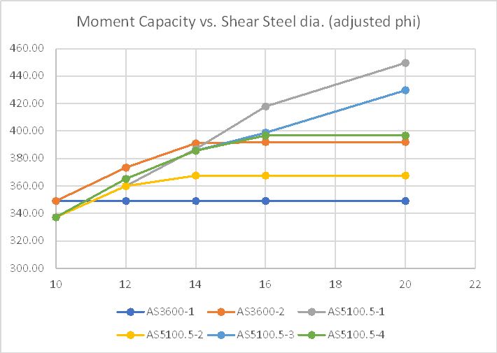
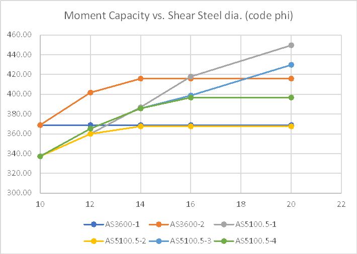
I have updated the graphs I posted previously to compare AS3600 with AS5100.5, with and without the limit. In the graphs below the loadcases are:

AS3600-1: Longitudinal force due to shear to AS 3600 with Theta values set to minimum.
AS3600-2: As above with Theta adjusted so that shear capacity = applied shear, up to a maximum of 50 degrees.
AS5100-1: Longitudinal force due to shear to AS 5100.5, with Theta set to minimum value and no limit on Vus.
AS 5100-2: As above but phi.Vus set with a maximum value of V*.
AS 5100-3: As ASS5100-1, but with Theta adjusted.
AS5100-4: As AS5100-2 with Theta adjusted.

With AS3600 reduction factors applied to both codes:
LongShear3-3_pcaiym.jpg


With applicable code reduction factors applied to both codes:
LongShear3-4_iilwqp.jpg


More details at:

In summary, if the limit on φVus is applied with the current code reduction factors then, at least for this one case, AS 5100.5 results are always equal to or less than AS3600, but if it is not applied they can be unconservative.

How this will change in the next amendment of AS5100.5 I don't know, but in the draft for public comment there was no change to the equation proposed.

Doug Jenkins
Interactive Design Services
 
Doug said:
It seems you also agree that the equation for the longitudinal force in AS 5100.5 is unconservative, because you agree that Phi.Vs should be limited to V*, as in the AASHTO and Canadian codes.

Doug,

If you refer back to your earlier posting dated 21 Sep 23 (see above quote) and go through my previous postings on you will notice that I did not ignore the missing restriction in the AS 5100.5 equation. The paper presented at the Concrete2023 conference held recently in Perth (see the reference Wong and Vimonsatit(2022) cited earlier in this thread also recommended that this missing restriction be included in AS 5100.5. It is possible that the AS 5100.5 Committee is already aware of this shortcoming which requires addressing before it is raised by us. If not, it is likely that they are aware of it now owing to the conference paper and our discussions in this thread.
 
The original Collins and Mitchell derivation of the longitudinal tension force uses the same base equations as the derivation of MCFT.

And it uses the equation

Vus = V* - Vuc

in it derivation. That is the restriction that should be applied.

I am sure Doug can confirm this.

The AS5100.5 committee has been told the errors in their shear rules many times over the last about 7 years since the first release with MCFT.
 
IDS said:
So what is your objection to the AS3600 equation then?

The paper by Vannisorn V, Wong KW and Mendis PA, Increase in longitudinal steel reinforcement to account for shear in RC beam design to AS 3600, Concrete Institute of Australia Conference Concrete2023 held in Perth 10-13 September 2023, stated that:

(1) the equation in Amendment 2 to limit phiVus = V* -phiVuc is not necessary as the amount of longitudinal steel determined in the old version is adequate to resist V*.
(2) Clause 8.2.7 AS 3600 could be revised and is not necessary to be included in AS 5100.5. The missing restriction "phiVus shall not be taken as greater than V*" found in other major standards should be included in AS 5100.5.
(3) The change in Clause 8.2.7 of AS 3600 to use "V*-phiVuc" instead of phiVus could be revisited. The changed equation is not suitable for load rating of shear particularly with loading resulting in shear deficiency, therefore need not be included in AS 5100.5.


Attached is a printout of my Excel analysis (to AS 5100.5-2017 with Amdt1) using the sections described in the blogs of IDS (links given earlier in this discussion thread).

My analysis fully conforms with MCFT for section shear in the determination of φV[sub]u[/sub] since I did not adjust the mid-depth strain. The strain used for my calculation of φV[sub]u[/sub] is equal to the strain calculated using the load effects of M* = 258 kNm and V* = 275 kN. To ensure consistency between the shear strength and the corresponding load effects (a key feature of MCFT),the strain 8.967E-4 is not increased in the analysis. The calculation for force in longitudinal steel uses the equation in the standard which does not have the restriction "φV[sub]us[/sub] not to be taken greater than V*".

Below are the findings.

(1) For a section (see Case 2) adequate for section shear and force in the the longitudinal steel for M*=258 kNm and V* = 275 kN, increasing the diameter of the shear reinforcement increases φV[sub]u[/sub] . The moment capacity phiMU (which is for pure flexure) remains the same and equals 472 kNm.

(2) Sections of Case 3, 4 and 5 are conservative for both the design to AS 5100.5 of section shear and the design of force in the longitudinal steel since φV[sub]u[/sub] /V* and A[sub]st.provided[/sub]/A[sub]st.required[/sub] are both greater than 1.0. Note that when stating whether a design is conservative or not, it is important to state clearly what it relates to.
 
 https://files.engineering.com/getfile.aspx?folder=27efc4d1-4497-49b7-9d3f-9aa53139b546&file=results_AS5100.5_checks.pdf
kww2008 - I have had a look at your calculations, and have the following comments:

1) It isn't clear what the point of the exercise was. The question being discussed is how the longitudinal force due to shear is affected by increasing the area of shear reinforcement, but in your example the most lightly reinforced section was adequate for both bending and shear, so of course the more highly reinforced sections will also be adequate. That does not show that the code is conservative.

2) You have compared your results with an M* of 258 kNm with my results with an M* of 400 kNm, so of course the results are different. If the AS 3600 equation for longitudinal force is used with that section, with all other factors according to AS 5100.5, then it finds that the shear capacity with 10 mm shear steel is as your calculation, and the longitudinal steel is adequate with a factor of 1.28. Note that your calculation of Ast_required is wrong. See details below.

3) The section capacity (PhiMu) to AS 5100.5 with zero applied shear is 445 kNm. I don't know where 472 kNm comes from. I don't agree that the moment capacity is not affected by increasing the shear reinforcement. The code is quite clear that the longitudinal steel area available for bending must be reduced by the area required to resist the longitudinal force due to shear, using a reduction factor of 0.7 (in AS 5100.5).

4) The result of the above is that the longitudinal steel has two different factors applied: 0.8 for the force due to bending and 0.7 for the force due to shear. In your calculation it appears that you have used 0.7 for the combined force. Note that in AS 3600 the reduction for bending (0.85 or 0.8) is applied to the combined force, and in overseas codes using partial factors there is of course only one factor applied to all forces in steel.

In response to general comments:
1) You have not provided any reasons for not adjusting the strain at mid-height. This is explicitly allowed in both AS 3600 and AS 5100.5.

2) Your frequently quoted quotes from your conference paper state that the current AS 5100.5 procedure for longitudinal force due to shear is adequate, and you appear to have used it without any limit in your calculations. It then immediately goes on to say that overseas codes have a limit on the value of Vus used, and this should be applied in AS 5100.5!

3) As stated previously, with the addition of the limit on the value of Vus the AS 5100.5 equation gives very similar results to the AS 3600 equation, applied with adjustment of the mid-height strain where necessary.

4) I don't agree that the AS 3600 equation is unconservative when applied to load rating analysis.

Doug Jenkins
Interactive Design Services
 
IDS said:
You have not provided any reasons for not adjusting the strain at mid-height. This is explicitly allowed in both AS 3600 and AS 5100.5.

My response here is to address the above comment. Since so many comments provided by IDS which require addressing, I will address them (most later) in separate posts to not overload readers with too much information in one post and to allow each to be discussed separately.

kww2008 said:
To ensure consistency between the shear strength and the corresponding load effects (a key feature of MCFT),the strain 8.967E-4 is not increased in the analysis.
Your first sentence in the quote is not accurate. The above is one of the reasons for not adjusting the mid-level strain. The other, not previously pointed out by me, is provided below.

While both codes allow the calculated mid-level strain (my value is 8.967E-4) to be increased up to 0.003 from the value calculated for M[sup]*[/sup] and V[sup]*[/sup] (my values are M[sup]*[/sup] = 258 kNm and V[sup]*[/sup] =275 kN) for calculating Θ[sub]v[/sub] and k[sub]v[/sub] (which is conservative for both load-rating and and design since the resulting φV[sub]us[/sub] and V[sub]u[/sub] are both smaller), it is not the intention of the standards for this adjusted value to be used to determine a new set of action effects. The allowed adjustment is just a simplification to enable a more conservative shear strength to be used. For design and load rating, it is the shear strength at your design load effects M[sup]*[/sup] and V[sup]*[/sup] that is of importance, not the strength for a set of load effects where one or more of the effects is different from the design values.
 
IDS said:
Your frequently quoted quotes from your conference paper state that the current AS 5100.5 procedure for longitudinal force due to shear is adequate, and you appear to have used it without any limit in your calculations. It then immediately goes on to say that overseas codes have a limit on the value of Vus used, and this should be applied in AS 5100.5!

I have not came across any published technical papers providing a reason for the inclusion of the mentioned restriction in standards. This restriction appears to be a "good practice" requirement. If this is correct, this means that a structural system designed to AS 5100.5 and not satisfying the requirement does not necessary fail to have the safety required by this standard. A well designed load testing program is required to shed more light on this. However, it is prudent to have this restriction included in AS 5100.5 in the next amendment or version of the standard, which is what the COncrete2023 paper proposed.

I have not came across a suitable analysis (assuming that this is even possible) which shows that a system is inadequate for force in the longitudonal reinfrcement as a result of not satisfying this restriction. Neither have I came across information of reported previous beam tests to show insufficient strength without the restriction.

The paper with the derivation of the equation for the area of longitudinal steel required for design (see paper titled "A general shear design method", by Collins, M.P., Mitchell, D., Adebar, P.E., and Vecchio, F.J. ACI Structural Journal,pp 36–45.1996) showed this equation without the restriction. A few papers and thesis quoting this equation also do not have this restriction which suggests it is very likely that this restriction was included in standards to promote "good practice".

In his blog stated "If the shear reinforcement area is increased well above the area required for the design shear force the AS 5100.5 equation gives bending capacity results that are highly unconservative"

As shown from the result of my excel attachment, for a set of load effects M* and V*, increasing the area required for the design loading has no effect on the bending moment. As described earlier, the resulting design is more conservative in regard to the current requirements of AS 5100.5 with increase shear reinforcement.
 
IDS said:
2) You have compared your results with an M* of 258 kNm with my results with an M* of 400 kNm, so of course the results are different. If the AS 3600 equation for longitudinal force is used with that section, with all other factors according to AS 5100.5, then it finds that the shear capacity with 10 mm shear steel is as your calculation, and the longitudinal steel is adequate with a factor of 1.28. Note that your calculation of Ast_required is wrong. See details below.

3) The section capacity (PhiMu) to AS 5100.5 with zero applied shear is 445 kNm. I don't know where 472 kNm comes from. I don't agree that the moment capacity is not affected by increasing the shear reinforcement. The code is quite clear that the longitudinal steel area available for bending must be reduced by the area required to resist the longitudinal force due to shear, using a reduction factor of 0.7 (in AS 5100.5).

4) The result of the above is that the longitudinal steel has two different factors applied: 0.8 for the force due to bending and 0.7 for the force due to shear. In your calculation it appears that you have used 0.7 for the combined force. Note that in AS 3600 the reduction for bending (0.85 or 0.8) is applied to the combined force, and in overseas codes using partial factors there is of course only one factor applied to all forces in steel.

Points 3 and 4 noted. When adjusting the spreadsheet for use with AS 5100.5 from a previous one I used based on AS 3600, a few of the equations were not corrected to those given in AS 5100.5. These errors are now corrected. The problem with using the equations of AS 5100.5 for longitudinal steel force is that additional steel is used instead of total steel with a single reduction factor Φ[sub]f[/sub]. This is the first study I did which uses the equations for force of AS 5100.5. I prefer the format of AS 3600 which uses total steel and a single factor. The AASHTO specification uses an individual factor for each action effect.

My findings are updated below. They are still basically the same as my previous findings except incorrect values have been corrected. Also two excel files are attached, one for M*= 297 kNm and another for M*=400 kNm (in response to IDS comment number 1). Also an independent check using the open software WXMAXIMA has been carried out for Case 2 M*=297 kNm and a printout of it is also attached.

---------------------------


My analysis fully conforms with MCFT for section shear in the determination of φV[sub]u[/sub] since I did not adjust the mid-depth strain. The strain used for my calculation of φV[sub]u[/sub] is equal to the strain calculated for the load effects in each case. To ensure consistency between the shear strength and the corresponding load effects (a key feature of MCFT),the strain is not increased in the analysis. The calculation for force in longitudinal steel uses the equation in the standard which does not have the restriction "φVus not to be taken greater than V*".

Below are the findings for the analysis using M* =297 kNm.

(1) For Case 2 adequate for section shear and force in the the longitudinal steel for M*=297 kNm and V* = 275 kN, increasing the diameter of the shear reinforcement increases φVu . The moment capacity ØM[sub]u[/sub] (which is for pure flexure) remains the same and equals 444 kNm.

(2) Case 3, 4 and 5 are conservative for both the design to AS 5100.5 of section shear and the design of force in the longitudinal steel since φV[sub]u[/sub] /V[sup]*[/sup] and A[sub]st.provided[/sub]/A[sub]st.required[/sub] are both greater than 1.0. Note that when stating whether a design is conservative or not, it is important to state clearly what it relates to, as shown here.

Below are the findings for the analysis using M* =400 kNm to address IDS comment that he used a moment of 400 kNm.

(1) Case 2, 3, 4 are all inadequate for force in the longitudinal steel for M[sup]*[/sup] =400 kNm and V[sup]*[/sup] = 275 kN. Increasing the diameter of the shear reinforcement increases φV[sub]u[/sub] . The moment capacity ØM[sub]u[/sub] (which is for pure flexure) remains the same and equals 444 kNm.

(2) Only Case 5 is conservative for both the design to AS 5100.5 for section shear and the design of force in the longitudinal steel since φV[sub]u[/sub] /V[sup]*[/sup] and A[sub]st.provided[/sub]/A[sub]st.required[/sub] are both greater than 1.0.

 
We did not publish the derivation of the formula other than its result in AS3600. All we were doing was deriving it from 1st principals as the C&M published version did not include all steps and gave a resulting longitudinal tension force top and bottom by dividing the total longitudinal tension force from shear by 2. We wanted to confirm this in the derivation, which we did. Your derivation says nothing about longitudinal tension force in the compression half depth. Ours and Eurocodes derivation both show it.

Any engineer who understands statics and equilibrium (you cannot have rotational equilibrium without vertical and horizontal force equilibrium) can derive it for themselves. We we do not chase Technical Publication and as this work on Standards is an unpaid sideline have other priorities like earning a living.

Obviously the FIB-Model Code writers have done the same, as they have the same resulting formula as us but have not published the derivation.

Collins & Mitchell derivation does not state the limitation with the final result, but if you follow through the derivation in their original text on it, they decided at one stage in the derivation to leave a Vs term in the equation, rather than Vc. The basis of this substitution was

V* = Vc + Vs

That is published. So Vs = V* - Vc.

It is not Vus as defined in the code as Vus assumes the stress in the shear steel is the yield stress. The maximum force that is available in the shear steel is Vu - Vc, the maximum force it can carry is Asv * fsv which is Vus in the code. But that is not the actual force in the shear steel, it is the maximum it can carry. In the calculation in the code, it is assumed the designer will want to use the minimum area of shear reinforcement so its stress is set at fsv. If Asv is increased above the minimum requirement from the code formula, that does not mean you can generate that extra force in the steel. It means that the vertical steel is at a lower stress than fsv.

For equilibrium, the force in the vertical steel cannot be greater than the force available at the section and that is V* - Vc.

I have no idea why they decided to leave Vs in and remove Vc in the C&M derivation, but it makes the resulting equation misleading in our opinion and open to abuse as to use it properly the engineer would have to realise that they have to calculate the real stress in the shear reinforcement rather than use the yield stress. If they had done the substitution the other way, they would have finished with our equation which is in AS3600. If the equation is to maintain the vertical steel force term, it needs to define a separate term, Vs = Asv fs where fs = (V* - Vc) / Asv (leaving out phi factors).

It is interesting that Looking at Eurocode based rules on it is misleading as Vc is set to 0 as soon as shear reinforcement is required, so Vus = V* in Eurocode logic, but the shear angle is reduced to 21.8 degrees so cot Theta is much larger. In their case, Vus would be limited to V*

 
kww2008 - Thankyou for the additional results. The results for M* = 400 kNm are broadly in agreement with mine, and show why using the AS 5100.5 equation with no limit to Vus is unconservative compared with both AS 3600 and the Canadian and AASHTO codes.

Firstly, when I say that a procedure is "conservative" in this discussion I mean that it will return section design capacity results no greater than those found using a more refined procedure, or other widely accepted procedures. I am not sure what you mean when you use that word.

Looking at the results with an M* of 400 kNm you agree that the current AS 5100.5 procedure indicates that the section with 20 mm shear steel is satisfactory for this applied moment, with a shear force of 275 kN, whereas the Canadian and AASHTO codes and AS 3600 indicate that it is not.

The current AS 5100.5 procedure is therefore not conservative.

There are many points in your posts above that I disagree with and which could be discussed further, but none of them change the facts listed above, which (based on your provided results) you agree with.


Doug Jenkins
Interactive Design Services
 
IDS,

IDS said:
The results for M* = 400 kNm are broadly in agreement with mine, and show why using the AS 5100.5 equation with no limit to Vus is unconservative compared with both AS 3600 and the Canadian and AASHTO codes.

I disagree with your statement above as my results do not show what you stated in the quote above. AS 3600 and the Canadian and AASHTO codes all have a different set of equations from that of AS 5100.5. AS 5100.5 has no restriction, AS 3600 with Admt 2 restricts φV[sub]us[/sub] to V*-φV[sub]uc[/sub] and both AASHTO and Canadian Codes restrict φV[sub]us[/sub] to not greater than V*. Owing to this, determining the degree of adequacy across these standards serves no useful purpose. Why use one of AS 3600, the Canadian or AASHTO codes as the reference for your comparison? If you used AS 5100.5 as the reference for comparison, you would have concluded that all three AS 3600, Canadian and AASHTO codes are overly conservative.

I have not come across any studies in the literature of suitable experimental studies which show that without the restriction of AASHTO and Canadian codes, the degree of safety required by AS 5100.5 is compromised. The restriction is likely a "good practice" requirement to limit excessive reduction of the amount longitudinal steel since the original equation developed by Collins and Mitchell in their published book "Prestressed Concrete" did not include the restriction of AASHTO and Canadian codes.

In the Concrete 2023 paper (by Vimonsatit, Wong and Mendis) presented in Perth recently, we alerted that the restriction in the current Canadian and AASHTO codes is missing in the current standard and should be included in the next revision of AS 5100.5. Please refer to the paper for more information.
 
rapt said:
Collins & Mitchell derivation does not state the limitation with the final result, but if you follow through the derivation in their original text on it, they decided at one stage in the derivation to leave a Vs term in the equation, rather than Vc. The basis of this substitution was
V* = Vc + Vs

That is published. So Vs = V* - Vc.

It is not Vus as defined in the code as Vus assumes the stress in the shear steel is the yield stress. The maximum force that is available in the shear steel is Vu - Vc, the maximum force it can carry is Asv * fsv which is Vus in the code. But that is not the actual force in the shear steel, it is the maximum it can carry. In the calculation in the code, it is assumed the designer will want to use the minimum area of shear reinforcement so its stress is set at fsv. If Asv is increased above the minimum requirement from the code formula, that does not mean you can generate that extra force in the steel. It means that the vertical steel is at a lower stress than fsv.

For equilibrium, the force in the vertical steel cannot be greater than the force available at the section and that is V* - Vc.

I have no idea why they decided to leave Vs in and remove Vc in the C&M derivation, but it makes the resulting equation misleading in our opinion and open to abuse as to use it properly the engineer would have to realise that they have to calculate the real stress in the shear reinforcement rather than use the yield stress. If they had done the substitution the other way, they would have finished with our equation which is in AS3600. If the equation is to maintain the vertical steel force term, it needs to define a separate term, Vs = Asv fs where fs = (V* - Vc) / Asv (leaving out phi factors).

While C&M derivation (Reference: Prestressed Concrete Structures by M P Collins and D. Mitchell, Response Publication Canada), 1997" made use of the equation for nominal shear resistance of a section V[sub]n[/sub] = V[sub]c[/sub] + V[sub]s[/sub] + V[sub]p[/sub] (Eqn 7-42, C&M's book) in the calculation in Section 7.13 of their book, they stated on page 372 "Because we are providing more stirrups than are required, we will determine the actual value of V_s at each section since an increase in V_s will decrease the required force in the longitudinal steel". C&M also pointed out that the equation for the required tension can be derived independently using a free-body diagram (see page 373, C&M's book) which is similar to the one used in AASHTO LFRD Bridge Design Specification (9th Edition). AASHTO LFRD referred to the caption of Figure C 5.7.3.5-1 as "Forces assumed in Resistance Model Caused by Moment and Shear". It is not an equilibrium model as can be seen from the use of the the inequality sign ">=" in the equation for the required tension force. Similarly, for section shear requirement for adequacy in AS 5100.5, the equation φV[sub]u[/sub] >= V[sup]*[/sup] where V[sub]u[/sub] =V[sub]us[/sub] + V[sub]uc[/sub] is not derived from considering forces using an equilibrium diagram; it is from a resistance model.


rapt said:
Your derivation says nothing about longitudinal tension force in the compression half depth. .
The magnitude of the additional tension force in the compression half depth of the C&M's approach is the same as the force in the tension half. As stated in your text above "resulting longitudinal tension force top and bottom by dividing the total longitudinal tension force from shear by 2". There is no need for me to repeat this derivation as it has already been described by C&M. This value for force is used in AS 5100.5 Clause 8.2.8 "Proportioning longitudinal reinforcement on the flexural compression side".


rapt said:
Obviously the FIB-Model Code writers have done the same, as they have the same resulting formula as us but have not published the derivation.
The equation for the additional force due to shear required for the longitudinal reinforcement in the flexural tensile chord is Delta F[sub]td[/sub] = (V[sub]Ed[/sub]/2)cot(theta), equation 7.3(34) for members with shear reinforcement in FIB - Model Code 2010. This equation appears to be derived using a "Variable Angle Truss Analogy" approach. The different types of truss models are described in this web link (
The equation of C&M for the additional force in the longitudinal reinforcement from shear is not from the truss analogy approach described above. As stated in C&M's 1997 text "Prestressed Concrete Structures", their equation (Eqn 7.62 in the text) is from the consideration of transmission of forces across a crack (Figure 7-37 of the text) and the assumption of yielding of the longitudinal steel and the shear ligatures.

rapt said:
It is interesting that Looking at Eurocode based rules on it is misleading as Vc is set to 0 as soon as shear reinforcement is required, so Vus = V* in Eurocode logic, but the shear angle is reduced to 21.8 degrees so cot Theta is much larger. In their case, Vus would be limited to V*
Eurocode 2 uses a Variable Angle Truss Model where concrete contribution to resistance is zero after cracking. The equation ΔF[sub]td[/sub] = 0.5 V[sub]ED[/sub] (Cot Θ - cot α) is from the model, not from the resistance model of AS 5100.5.
 
Bugbus said:
As a side question, I am interested to know everyone's approach when it comes to iteration. Do we try to match V* and phi*Vu directly, or are we trying to match V* and Vu, then apply the phi factor separately after the iterations are complete? So far I have been leaning towards applying phi after the iterations, but there has been some debate each way in my office. I understand that applying phi after the iterations tends to give (very) slightly more conservative results, though probably nothing meaningful.

Relating to the above, the two recently published papers for BEI 2024 listed below have information on the use of strengths for bridge assessments. They are accessible using the link below.

Wong and Vimonsatit (2024), "Determination of MCFT-Based Shear Strength for Shear Load Rating of
Concrete Bridges: The Effects of Using Load-Dependent Strengths", Bridge Engineering Institute Conference (BEI 2024), Journal of Bridge Engineering Institute, p.88-93.

Vimonsatit and Wong (2024), "Bridge Assessment Using MCFT- Determination of Load
Multiplying Factors for Optimal Shear Adequacy", Bridge Engineering Institute Conference (BEI 2024), Journal of Bridge Engineering Institute, p. 332-336.

Link
 
Status
Not open for further replies.

Part and Inventory Search

Sponsor