Eng-Tips is the largest engineering community on the Internet

Intelligent Work Forums for Engineering Professionals

AS 3600 AMDT 2 Equation 8.2.7(2) -continuing a previous thread

Status
Not open for further replies.

kww2008

Structural
Feb 1, 2008
149
0
0
AU
The thread744-499791 is closed. To continue discussing, I created this new thread.

In a former posting by Doug (IDS(Civil/Environmental)in the thread, he stated:

"Case 3 is just using the AS5100.5 code formula for the longitudinal force due to shear, and finding the adjusted bending capacity, allowing for the force. Increasing the shear reinforcement reduces the longitudinal force, so increases the bending capacity."
as a response to my query:
"Could you please describe the steps in your calculation for Case 3 which resulted in an increase in bending capacity from an increase in the area of shear reinforcement ?"

My understanding of the analysis described in Doug's blog (link provided in thread744-499791) is as below.

The total longitudinal steel A[sub]st1[/sub] is first determined for shear reinforcement A[sub]sv1[/sub]/s for a section with design shear V*[sub]1[/sub], ultimate shear strength V[sub]u1[/sub] such that the axial force in A[sub]st1[/sub] is close to f[sub]sy[/sub] under combined action effects M*[sub]1[/sub] and V*[sub]1[/sub]. The shear reinforcement is the increased to A_[sub]sv2[/sub]/s with the following values kept the same:
V[sub]u2[/sub] = V[sub]u1[/sub],
V*[sub]2[/sub] = V*[sub]1[/sub]
A[sub]st2[/sub] = A[sub]st1[/sub]
A new moment effect M*[sub]2[/sub] is then determined through trial and error (or iteration) so that A[sub]st2[/sub] is close to f[sub]sy[/sub].
Owing to M*[sub]2[/sub] determined being greater than M*[sub]1[/sub], it was concluded that an increase in the shear reinforcement caused an increase in "reduced moment capacity"

Doug,
Before I discuss further, I would like to check whether my description of the analysis above is accurate.
 
Replies continue below

Recommended for you

kww2008: Nothing wrong with your summary, but I'd add a few other points, that might clarify what is happening:

- When the ultimate shear capacity is exactly equal to the design shear force the AS 3600 equation gives exactly the same result as AS 5100.5.

- If the shear reinforcement has spare capacity the angle of the shear failure plane would have to be increased for the section to fail in shear.

- If the failure plane angle is increased, the longitudinal force due to shear is reduced, so the steel area available to resist bending is increased.

- You don't need iteration to find the moment capacity allowing for shear effects if you assume the applied shear is exactly equal to the shear capacity. You know the steel area available to resist bending effects, so you can find the moment capacity in the usual way.

- If you want to find the maximum shear and moment capacity for a given ratio of moment/shear, then iteration is required for that.

Another link with more details:


Doug Jenkins
Interactive Design Services
 
Thank you Doug for the prompt response.

For design to both AS 3600 and AS 5100.5, the design action effects M* and V* are known, and they have safety factors prescribed by these standards. If we provide shear reinforcement larger than the amount required for shear adequacy, this gives a value of φV[sub]us[/sub] such that φV[sub]u[/sub] is greater than V*. The requirement for design is φV[sub]u[/sub] >= V* [Eqn 8.2.1.6(1),AS3600]. There is no requirement for the shear reinforcement provided to yield at V*.

Angle Θ[sub]v[/sub] [8.2.4.2(5), AS3600) is determined using M*, V* and A[sub]st[/sub]. It is not dependent on the amount of shear reinforcement A[sub]sv[/sub]/s provided. Increasing the amount of shear reinforcement increases φV[sub]u[/sub] but has no effect on Θ[sub]v[/sub].

According to the MCFT, the shear capacity can be determined for any combination of applied shear and moment. For design to AS 5100.5 and AS 3600, and for design action effects M* and V*, the reduced ultimate shear capacity φV[sub]u[/sub] is calculated directly. For load rating of a load rating vehicle, at any stage of movement of the vehicle along the bridge, M* and V* can be calculated. The capacity φV[sub]u[/sub] also can then be calculated without iteration.

There is no single "actual shear capacity" for a section, even for a test structure with an increasing test load. For a test structure with an increasing applied load P such that both M[sub]n[/sub] and V[sub]n[/sub] increases proportionally with the load, at any stage (say i) of loading with action effects M[sub]ni[/sub] and V[sub]ni[/sub], the strength V[sub]nui[/sub] can be determined. To check experimentally the accuracy of the equation used for MCFT, one has to iterate to predict the load for shear failure P[sub]ui[/sub] with shear V[sub]uni[/sub] where V[sub]uni[/sub]=V[sub]ni[/sub]. This shear capacity V[sub]uni[/sub]=V[sub]ni[/sub] is not the actual shear capacity of the section:It is the shear capacity of the section only for action effects V[sub]ni[/sub] (=V[sub]uni[/sub]) and the coexisting M[sub]ni[/sub].


Iteration (to obtain V*=phiVu) is not necessary for design (to AS 3600 and AS 5100.5) and for the determination of load rating factors (to AS 5100.7) because for both activities the reduced ultimate shear capacity phiVu is calculated directly from M* and V*. The phiVu calculated directly without iteration is the capacity of the section with V*. This capacity is the "actual shear capacity" if one wanted to call it that. The capacity obtained using iteration does not give any useful information as the design requirement is V* =< phiVu, not V*=phiVu.
 
kww2008 - There is a lot of new stuff there, but I have no idea how it relates to your previous post or my response.

The main points I have made on this topic are:

1) The AS 5100 equation for longitudinal force due to shear is highly unconservative because it doesn't place any limit on Vus.
2) The AS 3600 version may be very conservative if used with the minimum value of Theta because it doesn't allow for any effect of shear steel area being greater than required.
3) Adjusting the theta value with the AS 3600 formula removes this conservatism, and is consistent with results from the AASHTO and Canadian codes.
4) If you are checking a known section with known reinforcement and known V* and M* values, no iteration is required.
5) For checking sections with many different possibly critical load cases it is straightforward to generate a shear/moment interaction diagram.

Do you disagree with any of that?

Have I missed any problems with designing for shear/moment?


Doug Jenkins
Interactive Design Services
 
Doug,

Thank you for your comments.

Point 1
In your blog, you recommended that the value of ØV[sub]us[/sub] to be limited to V*. This restriction of "ØV[sub]us[/sub] not to be taken greater than V*" was accidentally left out in AS 3600 with amendment 1 and in AS 5100.5 since a similar restriction is present in AASHTO and the Canadian design standard. In a recent paper presented in the Concrete2023 conference held in Perth (which you attended), reference listed below, we also recommended that this missing requirement be included in AS 5100.5 and to the relevant equation in AS 3600 with amendment 1 (if reinstated). So we both agree that the equation of AS 3600 Amendment 2 can be conservative.

Although I could not find the reason for the restriction similar to "ΦV[sub]us[/sub] not to be taken greater than V*" in AASHTO and the Canadian standard, it is prudent to include it in AS 5100 to limit the amount of reduction of longitudinal steel.

(Vannisorn V, Wong KW and Mendis PA, Increase in longitudinal steel reinforcement to account for shear in RC beam design to AS 3600, Concrete Institute of Australia Conference Concrete2023 held in Perth 10-13 September 2023)

"The AS 5100 equation longitudinal force due to shear is highly unconservative" is not strictly accurate. In design to AS 5100.5, one has to meet all requirements. The three key requirements for a section with shear and bending are
(a) flexure: φM[sub]u[/sub] > = M*
(b) section shear: φV[sub]u[/sub] > = V*, and
(c) block rotation : stress from the force in the longitudinal steel <= f[sub]sy[/sub].

If A[sub]sv[/sub]/s is increased and the amount of longitudinal steel is reduced to satisfy (c), one must go back to check whether the total steel provided still satisfies (a) and (b). If we provide total A[sub]st[/sub] which satisfies all three requirements currently in AS 5100.5 and AS3600 with amendment 1, we expect that the section under the design action effects has adequate safety to these standards for bending, section shear and block rotation.

If the design is carried out in sequence (i.e. not iteratively) by reducing the longitudinal steel in (c), increases A[sub]sv[/sub]/s and fails to go back to check that both (a) and (b) are met, then the design is unconservative.


Point 2
We both agree that the equation in AS 3600 amendment 2 may result in excessive longitudinal reinforcement.

In the conference paper, it was stated that the AS 3600 Amendment 2 equation unnecessarily "removes the flexibility in setting the proportion of the amount of shear reinforcement to additional reinforcement for cost optimisation and to ease congestion of longitudinal reinforcement". Also "it may result in the provision of an excessive amount of additional reinforcement in comparison with the amount determined using the previous equation".

Not sure what you meant by "minimum value of theta" as Θ[sub]v[/sub] is determined in AS 3600 from M* and V* and the total A[sub]st[/sub] provided.

Point 3
I do not follow what you meant by "adjusting the theta value". The only limit in AS 3600 to Θ[sub]v[/sub] is from ε[sub]x[/sub] <= 3E10-3 [Eqn 8.2.4.2(5), AS 3600] which is a requirement for section shear. This limits Θ[sub]v[/sub] to 50 degrees.

Point 4
Agree

Point 5
Disagree.

The interaction diagram using the section-shear equation for MCFT is an MCFT interaction diagram. It is not necessary for design or load rating as one determines the reduced ultimate shear strength ∅V[sub]u[/sub] directly from M* and V* (without the use of iteration).

The M* on the MCFT interaction line is not a "moment capacity". It is the coexisting action effect with V* for shear adequacy, i.e V*=∅V[sub]u[/sub]. The term "reduced moment capacity" should be limited to ∅M[sub]u[/sub].

If the calculated ∅V[sub]u[/sub] <> V*, this value cannot be obtained from an interaction diagram. This calculated value is the "actual" shear strength of the section with M* and V*. An interaction diagram is not required to check shear adequacy of a section with action effect M* and V*. if V* <= ∅V[sub]u[/sub], the section is adequate (inside or on the interaction line) for section shear. If V* > ∅V[sub]u[/sub], not adequate (outside the interaction line).


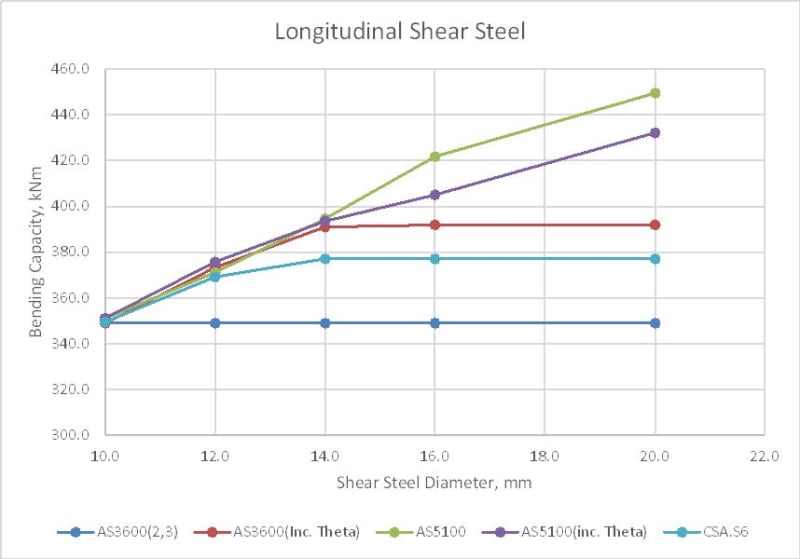
I think it is worth looking at my plot of the moment capacity to different codes:
longshear1-1_w7umhq.jpg


The top line complies with all the current requirements of AS 5100.5, but if the restriction on Vs was included it would come down to the light blue line (Canadian code). How is that not unconservative?

Although I could not find the reason for the restriction similar to "ΦVus not to be taken greater than V*" in AASHTO and the Canadian standard,

The reason is that the force in the shear steel cannot be more than the applied shear force. But it seems that you agree that AS 5100.5 should be changed anyway.

For AS 3600 I agree that the equation can be over-conservative if applied without adjusting theta, but with adjustment of theta it is less conservative than the Canadian and AASHTO codes, whilst still complying with the requirements of MCFT.

The procedure for adjusting Theta is:
1) Find the angle (and associated strain) such that phi.Vu = V*.
2) If that is greater than 50 degrees then set Theta to 50 degrees and strain to 0.003.
3) Calculate the longitudinal force due to shear with the new Theta.
4) Find the moment capacity allowing for this force.

Note that AS 3600 explicitly allows the longitudinal strain to be increased above the calculated minimum value (Cl. 8.2.4.2.2), up to a maximum of 0.003. The only reason I can think of for doing that is to reduce longitudinal steel forces by taking advantage of available vertical reinforcement capacity, by increasing Theta.

I don't follow your objection to using an interaction diagram. For any point on the line the moment is equal to the section moment capacity with the associated applied shear force. Any point inside the line will have a greater shear and bending capacity than the applied actions.

Doug Jenkins
Interactive Design Services
 
kww2008,

If you look at the theoretical development of the MCFT by Collins etc,

in determining the longitudinal tension force, they came up with a formula that included a term

2Vc + Vs.

They decided to then use the equation V* = Vc + Vs, reworked to Vc = V* - Vs

to remove the Vc from that longitudinal tension force calculation with the assumption that the shear reinforcement is at yield.

In this Vs is not the capacity of the vertical stirrups, it is the force that can be carried by the stirrups under the loading. The stirrups cannot create vertical force.

If more stirrups are provided than are required for the vertical force at the section, the stress in those stirrups will be less.

Your error is in assuming that Vus = Asv fsv

It should be fs.

In AS3600 formula for Vus, that does not matter in the shear capacity calculation. But when Vus from the code formula based on fsv is used in the longitudinal force calculation, it does matter, and Vus in that case should be based on fs, not fsv

Vus can never be greater than the applied shear force the stirrups are carrying.

In AS3600, it was decided, instead of removing Vuc from the initial formula above, and then requiring designers to calculate the actual stress in the vertical reinforcement, we would remove Vus. The result is exactly the same, if fs is used correctly in the Vus formulation

Part of the reason was exactly the mistake you are making, assuming the stirrups are at yield. There were instances seen in design checks where designers had reduced the longitudinal tension force to zero by providing large quantities of vertical reinforcement.

I have explained this several times. Other codes have not picked up the difference between their formulae and the original MFCT development and formulation.


Rapt,

Thank you for your comments.

The equation for the block rotation (a term I have been using for this potential failure mode) is from the AASHTO bridge standard as described in one of my earlier posts. It was developed using a free body diagram, and used a few simplifying assumptions. One of these is that the contribution of the resistance from the concrete to the rotating body is small owing to its small lever arm about the point where the block rotates and can be ignored.

Much of the work of Collins et al is for the developments of the CFT and MCFT, and it was for research purposes to come up with equations to check the accuracy of equations from these theories through laboratory testings. These equations are able to predict forces and strains over the entire range of loading to enable the researchers to verify the accuracy of their equations.

The free body diagram used for block rotation appears to be similar to those used for "strut and tie" design to ensure sufficient amount of reinforcement is provided to prevent failure. For shear, the design requirement is adequate capacity at V*. There is no ductility requirement for shear so both the longitudinal steel and the shear reinforcement do not have to yield at V*.

It was pointed out in the conference paper by Vannisorn, Wong and Mendis (reference given in my earlier post) that "the longitudinal steel determined using Equation 8.2.7.1 in AS 3600 with amendment 1 is based on the available resistance from the yielding of the provided shear reinforcement and the design shear V*. It is also not expected to fail with the failure mode depicted in the free body diagram before V equal to V*". This equation uses V[sub]us[/sub] to determine the amount of longitudinal reinforcement that has to be provided to prevent failure through block mechanism at V*. The term φV[sub]us[/sub] is the potential resistance available from the shear reinforcement provided. It is not the force in the stirrups at V*. By providing the steel determined using this equation, the design is adequate for block rotation.

You stated "There were instances seen in design checks where designers had reduced the longitudinal tension force to zero by providing large quantities of vertical reinforcement.". I think you meant the additional tension force required for the effect of shear. This is because the restriction of "φV[sub]u[/sub]s is not to be taken to be larger than V*" found in AASHTO and CSA standards (to prevent excessive reduction in the amount longitudinal reinforcement) was missing. It is recommended in the conference paper that this restriction be included in AS 5100.5.

It should be pointed out that after reducing the total amount of longitudinal reinforcement to satisfy block rotation, designers should should go back to check that the section-shear requirement is still met if design checks are carried out sequentially.


CFT might have been a research exercise, MCFT was a move to make that a section design approach, the development of the final equations for SMCFT (Simplified Modified Compression Field Theory) were not. They were to simplify the application of the theory into a codifiable form.

The ASSHTO Diagram is not complete. We started with that. There are a few actions missing to satisfy statics!

You cannot base the calculation on the assumption of steel yield if the stresses are never sufficient to cause yield. Compatibility and Statics have to be satisfied.

I meant what I said, longitudinal tension force for shear was calculated as zero at a location where the longitudinal tension force for flexure was also 0, so the total longitudinal tension force was 0, so no development was required!

 
Doug,

Thank you for your comments. Several queries.

(1) Are all your plotted points optimally adequate for section shear (i.e having V*=φV[sub]u[/sub]) ?

(2) In your procedure for adjusting theta, you mentioned about getting theta greater than 50 degrees for φV[sub]u[/sub] = V*. How is it possible to get theta > 50 degrees when the standards do not allow ε[sub]x[/sub] to be larger than 3E-3 in the calculation of φV[sub]u[/sub] ?

(3) Does any of you points satisfy optimal adequacy for both block rotation (f[sub]s[/sub] = f[sub]sy[/sub]) and section shear V*=φV[sub]u[/sub] ?
 
kww2008

I have just gone back through the development of the method, where they determine all forces from statics of the actions on the member. As the Collins work did not show the full derivation, and there were some questions that could not be answered without it, especially regarding the effects at end supports compared to sections along the member, we developed it again from 1st principles to confirm their results and answer our questions and achieved the same result as the original Collins et al work.

From this they determined,

Longitudinal tension force at the tension face
Asy fsy = (Vc + .5 Vs) cot theta

In this original form developed from the static equilibrium of the actions at the section, if you were to use the logic that Vs = Asv fsv, then adding extra vertical reinforcement would actually increase the longitudinal reinforcement requirement.

They then re-arranged the formula, using V* = Vc + Vs, so Vc = V* - Vs to substitute for Vc in the formula.

This resulted in Asy fsy = (V* - .5Vs) cot Theta.

They used the further logic that V* = Vu / phi to come up with their final formula

Ast fsy = (Vu / phi - .5 Vs)cot theta

The only way both of the substitution assumptions they made are correct is if V* = Vc + Vs.

Your interpretation of the reliance on Vs to reduce the longitudinal reinforcement is exactly the opposite of the actual calculation.

The AASHTO diagram does not even have a Vc force component from memory and neither does it include any moments at the section.


Rapt,

Thank you for your comments.

The AASHTO equation is described in a published paper titled "Longitudinal Steel Stresses in Beams Due to Shear and Torsion in AASHTO-LRFD Specifications" by Rahal N, published in ACI Structural Journal, 2005. This paper can be found on ResearchGate. Results from test beams show that the equation can predict accurately the longitudinal steel strains (with the term V_s in the equation). There is no mention of the equation requiring an assumption of V_c = V_u/phi - V_s to derive it. The use of V_s directly in the equation used to predict strains for the tests shows that there is no need to have the term V_s restricted to 'V_u/phi -V_c' for the equation to be accurate.

The AASHTO has the force V_c component shown next to the failure surface but not labelled since not used in developing the equation. It diagram does not include any moments at the section because this free body is for the determination of the force from shear. The force from moment is determined separately using the term M_u /(phi dv).


(1) Are all your plotted points optimally adequate for section shear (i.e having V*=φVu) ?

No, the whole point of the exercise is to investigate the effect of increasing the area of shear steel so that V* < φVu. When V*=φVu the AS 3600 and AS 5100 equations give the same result.

(2) In your procedure for adjusting theta, you mentioned about getting theta greater than 50 degrees for φVu = V*. How is it possible to get theta > 50 degrees when the standards do not allow εx to be larger than 3E-3 in the calculation of φVu ?

No, εx can vary between the minimum value given by the equations and 0.003, as stated in the code, so the maximum value of Theta is 50 degrees. That is why the moment capacity line using AS3600 + adjustment of Theta flattens out at 14 mm in the graph plotted in my previous post, but the AS 5100 lines continue to increase.

(3) Does any of you points satisfy optimal adequacy for both block rotation (fs = fsy) and section shear V*=φVu ?

Aa above, we are looking at the cases where AS 5100 gives unconservative results for bending when the shear steel has been increased so that V* < φVu, but for a shear steel diameter of 10 mm V*=φVu and all the codes give the same result.


Doug Jenkins
Interactive Design Services
 
I will see if I can get a copy.

The formula in MCFT for longitudinal tension force is derived from the same force diagram and compatibility equations that were used to derive the formulas for the calculations of the strains for the calculation of Vuc and uses a combined effect of applied moment and shear, which is the basis of MCFT.

It is not the same force diagram as is shown in AASHTO for longitudinal tension force into an end support as it includes both co-existing applied moments and applied shears and Vc and is applicable at any point along the member, not just at the end support. And from memory the best way to resolve the forces was moments about the support point, in which case , as you investigate points away from the support, the effect of Vc is not insignificant as the AASHTO discussion suggests.

And produces equals longitudinal tension force due to shear in the top and bottom as is defined in MCFT and AS3600 and even Eurocode 2.

AASHTO appears to not have a longitudinal tension force from shear at the compression face.
 
IDS,

Thank you for your prompt response.

Since you did not assume φV[sub]u[/sub] = V*, I wonder what assumption(s) you used to determine M* for a new A[sub]sv[/sub] and how optimally you have designed for section shear and block rotation.

If I can see the values for the listed variables below for the first two points of the AS 5100.5 line, that will help me to understand better your study.

M*
V*
φV[sub]u[/sub] (since not equal to V* for the second point)
f[sub]st[/sub], the force in the longitudinal steel from combined action M* and V*

Also if possible,
A[sub]st[/sub]
width B
depth D
effective depth d
A[sub]sv1[/sub] used

 
Since you did not assume φVu = V*, I wonder what assumption(s) you used to determine M* for a new Asv and how optimally you have designed for section shear and block rotation.

I should clarify what I meant there. I was looking at cases where φVumax > V*. In that case the strain and associated Theta were calculated such that φVureduced = V*. If the adjusted Theta was <= 50 then that value was used, otherwise 50 degrees was used.

Either way, a new longitudinal force due to shear was calculated using the AS 3600 formula, and this was used to find the reduced moment capacity. If φMuadjusted >= M* then the section is OK, and if it is < M* it isn't.

Note that for the interaction diagram an iterative calculation is required since the points on the curve are found for specified values of M*/V*, so after φMuadjusted is calculated the calculation needs to be repeated for a new V*.

If I can see the values for the listed variables below for the first two points of the AS 5100.5 line, that will help me to understand better your study.

I'll have a look and either post the values or the complete spreadsheet.


Doug Jenkins
Interactive Design Services
 
Doug,

Considering more than 1 mode together is confusing when using an interaction diagram. I therefore limit my discussion below to section shear effect.

Say, for the solution for point 2, you use an interaction diagram for A_sv2/s. And you iterate along the line from the origin of the diagram maintaining the relation M*/V* for the point (V1*,M1*), and this line intersects with the interaction diagram. Say, the values you get from the intersection point are M*_intersect,V*_intersect and phiVu_intersect. M*_intersect is not a "reduced moment capacity" of (V1*,M1*). It is the coexisting design moment with design shear of V*_intersect, and for these effects, the ultimate shear capacity is phiVu_intersect.

Before you spend more time on this, I better check with you whether the above steps were used to get point 2 since you mentioned M*/V*. If you did, the coexisting moment (your "moment capacity") you get for point 2 is for a different design shear, not for V1*.
 
Before you spend more time on this, I better check with you whether the above steps were used to get point 2 since you mentioned M*/V*. If you did, the coexisting moment (your "moment capacity") you get for point 2 is for a different design shear, not for V1*.

I mentioned M*/V* with respect to creating an interaction diagram, where iteration is required.

For checking a section for a specified V* and M* the procedure is:

1) Find the mid-height strain for V* and M* and then find the associated Phi.Vu.
2) If Phi.Vu < V* then the section doesn't work.
3) If Phi.Vu > V* then find the mid-height strain such that Phi.Vu = V*, and the associated adjusted Theta.
4) Using the lesser of the adjusted Theta or 50 degrees, find the section Phi.Mu, including allowance for longitudinal load due to shear.
5) If Phi.Mu >= M* the section is OK. If it isn't the section doesn't work.
6) Finished.

Say, for the solution for point 2, you use an interaction diagram for A_sv2/s. And you iterate along the line from the origin of the diagram maintaining the relation M*/V* for the point (V1*,M1*), and this line intersects with the interaction diagram. Say, the values you get from the intersection point are M*_intersect,V*_intersect and phiVu_intersect. M*_intersect is not a "reduced moment capacity" of (V1*,M1*). It is the coexisting design moment with design shear of V*_intersect, and for these effects, the ultimate shear capacity is phiVu_intersect.

I don't know what you mean by "iterate along the line from the origin". If I create an interaction diagram I then plot all the M*, V* points, and those inside the line are OK, those outside are not.

Doug Jenkins
Interactive Design Services
 
Doug,

In your step 3, you have to assume a relation between M* and V* to be able to get V* = phiVu. I think you used the ratio of M*/V*. At the end of this step, the design shear is same as the ultimate shear strength V*_intersect = phiVu_intersect. The design moment is
M*_intersect = M*/V* x V*_intersect. This adjustment is what I mean by "iterate along the line from the origin". At the end of the adjustment, M* and V* are on the interaction line.

My understanding of MCFT and the use of AS 5100 for design of your point 1 and 2 AS5100case is :

When you increase the shear reinforcement from Asv1 to Asv2, for a set of design actions (M*,V*),.
For 2
Bending capacity phiMu no change from 1 since no change in Ast.

Shear capacity phiVu increases as a result of the increase of shear reinforcement from N10 to N12
phiVuc and theta_v - no change since they depend on M*, V* and Ast only, not Asv.
phiVus increases owing to the increase in Asv from Asv1 to Asv2

MCFT is a theory for shear capacity, and this capacity is determined using the applied action effects (not factored up [or down] action effects), so no iteration (adjustment of strain to give V*=phiVu) is required. The theory cannot determine bending capacity.

I reproduced below a block of text from one of my earlier posting (with correction) to illustrate this:

"There is no single "actual shear capacity" for a section, even for a test structure with an increasing test load. For a test structure with a monotonically increasing applied load Pi such that both Mni and Vni increase with the load, at any stage (say i) of loading, the shear strength Vnui can be determined. To check experimentally the accuracy of the equation used for MCFT, one has to iterate (numerically) to predict the load for Pui when the shear Vni where Vuni=Vni. Note that this iteration uses the characteristic of the loading, i.e. Mni/Vni is assume constant. This strength Vni=Vuni is not the actual shear strength of the section:It is the shear capacity of the section only for the level of loading where the action effects are Vni (where Vni=Vuni) and the coexisting Mni."

The subscript "n" indicates nominal or unfactored.

For design (and for load rating of a rating vehicle),and for a section with M* and V*, the only ultimate shear capacity of relevance is the phiVu determined without iteration. The action effects are factored up. So if V* < phiVu, section-shear is adequate.


n your step 3, you have to assume a relation between M* and V* to be able to get V* = phiVu. I think you used the ratio of M*/V*. At the end of this step, the design shear is same as the ultimate shear strength V*_intersect = phiVu_intersect. The design moment is
M*_intersect = M*/V* x V*_intersect. This adjustment is what I mean by "iterate along the line from the origin". At the end of the adjustment, M* and V* are on the interaction line.

No, that is not the procedure I am following. The graph of Moment Capacity against bar diameter shows the design moment capacity (Phi.Mu) for a specified and unchanging V*. That is why all the lines other than AS 5100.5 flatten out when phi.Vu with Theta = 50 degrees > V*.

For generating an interaction diagram you need to iterate to find each point on the line but having done that you just plot each load point from the analysis using M* and V*, which seems to be entirely consistent with your final statement:

For design (and for load rating of a rating vehicle),and for a section with M* and V*, the only ultimate shear capacity of relevance is the phiVu determined without iteration. The action effects are factored up. So if V* < phiVu, section-shear is adequate.

... subject to M* < phiMU of course.

So given that we agree on that, I have no idea what your point is.

Doug Jenkins
Interactive Design Services
 
Status
Not open for further replies.
Back
Top