Eng-Tips is the largest engineering community on the Internet

Intelligent Work Forums for Engineering Professionals

AS3600 Boundary elements in moderately ductile shear walls

Status
Not open for further replies.

li0ngalahad

Structural
May 10, 2013
86
0
0
AU
Hi all,

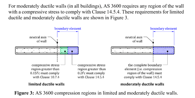
I had a discussion with a colleague about the requirements for boundary elements in limited and moderately ductile shear walls. According to the code, boundary elements are required wherever the peak stress in the wall exceeds 0.15 f'c. The debate revolves around which earthquake load should be used for this check: the elastic load (mu=1, Sp=1) or the design earthquake load (mu=2; mu=3 and Sp=0.77; Sp=0.67). The code states, "The stress referred to in Item (b) shall be calculated using the design action effects for the strength limit state, a linear-elastic strength model, and the gross cross-section properties of the wall." This seems to imply that the reduced forces should be used, not the elastic forces, which has always been my understanding.

My colleague noted a potential issue: if a limited ductile wall requires boundary elements because the stress exceeds 0.15 f'c, the structure could be reclassified as a moderately ductile wall system. This reclassification would significantly reduce the earthquake design actions, potentially bringing the stress below 0.15 f'c, and thus not requiring boundary elements. This creates a paradox where a shear wall with higher assumed ductility would require fewer boundary elements than one with lower assumed ductility, which doesn't seem logical.

This raises the question of whether we should assess this stress based on the fully elastic response (mu=1, Sp=1), similar to the process when checking if any portion of the wall experiences tension (which requires designing the wall as a column). The problem is that the code specifically advises against this!

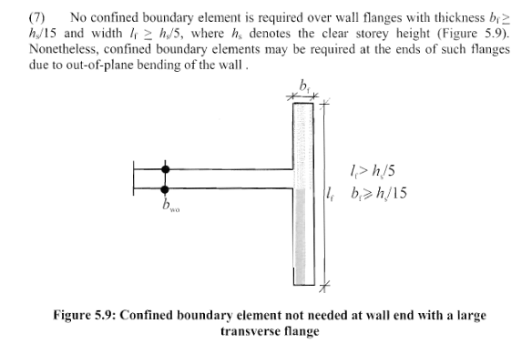
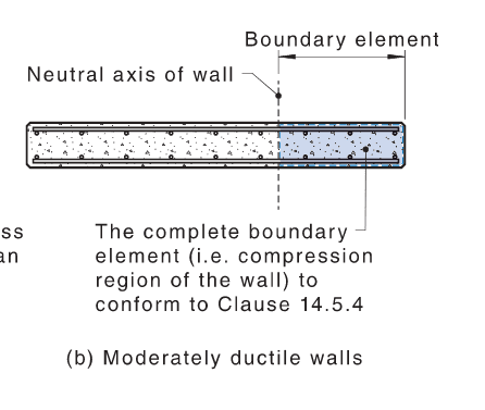
Another point to consider, which could help resolve the above paradox, is the interpretation of clause 14.7.1 (b), which states, "Moderately ductile structural walls shall conform with Clauses 14.6 except [...] in Clause 14.6.2 all vertical reinforcement in boundary elements shall be restrained in accordance with Clause 14.5.4 irrespective of the calculated compressive stress." This could be interpreted so that boundary elements need to be detailed at all levels, at all wall ends, corners, and intersections, even where compression forces are minimal.

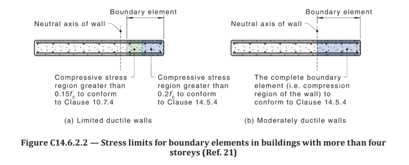
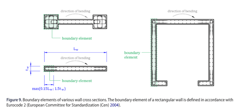
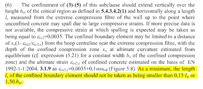
I've always interpreted this clause to mean that, for moderately ductile walls, detailing according to 14.5.4 applies without distinguishing between 0.2 f'c and 0.15 f'c, but the boundary element zone would still be designed only as the zone where stress exceeds 0.15 f'c. However, this discussion has left me uncertain, and I wonder if the clause implies that boundary elements are required everywhere, even for stresses below 0.15 f'c. If so, what should be the length of the boundary element if no stress check is required? Should it be the greater of 0.15 Lw and 1.5 bw, as per the critical tension zone for minimum longitudinal reinforcement? The code and commentary don't seem to specify this at any point.

I'd appreciate your views on this and how you interpret these clauses in the code.
 
Replies continue below

Recommended for you

P.S. I was also reading the Shear wall design manual in CSi ETABS, and their interpretaion is similar to my original interpretation, which I'm not too sure about anymore:

- use design reduced loads
- boundary element required when stress exceeds 0.15 f'c
- detail to 14.5.4 within the boundary element irrespective of the stress

in addition, CSI calculates the boundary length as 0.15 Lw or 1.5 bw (which is not stated in the code)

Screenshot_2024-07-26_115313_crnjvl.png

Screenshot_2024-07-26_115327_c7seqj.png
 
This seems to imply that the reduced forces should be used, not the elastic forces, which has always been my understanding.

"Linear elastic" and "gross cross-section" would suggest to me it's based on the elastic forces prior to any cracking or hinges forming. I don't like how the wording talks about "design action effects for the strength limit state" though, as the strength limit state for a particular element would be after the reduction for that element.

----------------------------------------------------------------------

Why yes, I do in fact have no idea what I'm talking about
 
Just Some Nerd said:
"Linear elastic" and "gross cross-section" would suggest to me it's based on the elastic forces prior to any cracking or hinges forming. I don't like how the wording talks about "design action effects for the strength limit state" though, as the strength limit state for a particular element would be after the reduction for that element.

I somewhat agree, however I feel like if that was the case they would have clearly specified this, as they do for example in clause 11.2.1 (see below - but there are other clauses with similar wording)

Screenshot_2024-07-26_121914_kdsvt5.png


The fact that the code specifically refers to "design action effects for the strength limit state" without specifying further, and that commentary also doesnt mention anything on this regard makes me think the intent is to actually use reduced loads.
 
On second read I don't think you could ever end up with less boundary elements moving to moderately ductile. The commentary explicitly states/shows that the entire compressive zone of a wall will be a boundary element detailed to 14.5.4 irrespective of the stress
boundary_zq2oa2.png


My intuition/understanding of ductility still tells me that we should be confining the end of the wall to ensure hinge formation, i.e. it should be targeting the stresses prior to the hinge forming to make sure that actually happens. I'm not sure how the logic applies to compressive stresses given I'm usually more acquainted with the focus on shear overstrength, but I'm assuming it's a similar deal where there's a need to guarantee no failure

----------------------------------------------------------------------

Why yes, I do in fact have no idea what I'm talking about
 
It is meant to be performed using the ductility factor and structural performance factor assumed by the designer.

Where 1 and 1 are required, the code specifically says so.
 
@Just Some Nerd

Yeah, actually, I saw that the other day after posting this. I had seen it before but never realized the second part of the figure was showing the boundary element starting at the neutral axis.

I've found the paper referenced in the commentary. It can be accessed here: and it shows this:
Screenshot_2024-07-29_171000_jhs4nf.png


Honestly, it makes little sense to me. First, the code doesn't really say that. Second, this would mean MDW would require boundary elements everywhere, from base to roof, on any lateral resisting wall/core, as there is always a seismic case where the full wall is in compression since earthquakes are fully reversible and can act in any direction. Even the gravity case alone (G+0.3Q with no earthquake) will put the full wall in compression. If the intention of the committee was really to have boundary elements everywhere, they surely would have said so explicitly and not in this ultra-confusing way. Currently, as far as I know, no code requires confined boundary elements for the full extent of lateral resisting walls regardless of the stress and/or strain. In my opinion it's just very conservative, expensive, and unnecessary.

I also found another paper (funnily enough, presented at the same conference as the paper above) that discusses these stress limits, showing how they are inconsistent and overly conservative for any assumed ductility level. Coincidentally, in the paper, they interpret the clauses the same way I do (0.15f'c defines the boundary elements for both LDW and MDW, second page), and they also point out the paradox where we could end up with fewer boundary elements with MDW than with LDW (page 11). The paper can be found here:
@rapt
Yes, understood, and it makes sense they would specify when we need to use 1 and 1. Do you have an opinion to share on the rest of the discussion? In your view, do boundary elements really need to be applied at all points where the wall is in compression for MDW, and therefore everywhere in a shear wall? Or should we still check where the stress is >0.15 f'c to define where boundary elements are, but detailing would be for 14.5.4 no matter what the stress is within the boundary zone (my original interpretation)?

Thanks in advance.
 
Even the gravity case alone (G+0.3Q with no earthquake) will put the full wall in compression.

As you are not relying on ductility for the gravity case it does not govern the boundary elements.

Also, remember that the boundary elements are only required at discontinuous edges of walls and around openings.
 
rapt said:
14.6.2.1 specifically says when boundary elements are required in each storey.

Yeah I can read that but that wasn't the question. My question is, to you or whoever wants to share their interpretation, does 14.7.1 (14.5.4 irrespective of stress) apply to the BE definition (14.6.2.1) or only to the detailing within the BE (14.6.2.3)? If it's the first one then 14.5.4 is to be applied pretty much everywhere. If it's the second one, 14.5.4 is to be applied where we exceed 0.15f'c, but we could end up with less BE's in MDW than in LDW, which is a paradox.


Retrograde said:
As you are not relying on ductility for the gravity case it does not govern the boundary elements.

Also, remember that the boundary elements are only required at discontinuous edges of walls and around openings.

I wasn't implying we shoudl apply ductility detail to gravity cases, I was saying that if we need to apply 14.5.4 wherever we have compression stress, then it goes everyhwere because there will be always a seismic case where we have compression stress at any point of the wall, and in fact the smaller the seismic load is, the more will be the portion of wall in compression (neutral axis outside of the wall section), to the extreme that if the seismic load is zero , the the whole wall is in compression and therefore we need 14.5.4 everywhere

On your second point, if we take the image from the commentary, in an isolated shear wall we need to consider as bondary element the whole zone past the neutral axis, which means the whole wall for the reason I explained above.
For a core this is not clear, does a corner constitute a discontiuity? I have seen some interpretations like the one below (form the paper RC walls in Australia: seismic design and detailing to AS 1170.4 and AS 3600 by Menegon Wilson Lam and McBean) where in a core the whole side of the wall is considered as boundary element (and I believe they are considering the wrong side becasue the moment direction indicates that the green zone is in tension, not compression). The funny thing is they mention the Eurocode in the caption, however EC8 (not 2, which has no BE definiotns) has a definition of boundary element opposite to this one, where they basically say a return wall in NOT a boundary element (second screenshot).
Once again, lack of transparency on the code leads to confusion of engineers, and even reasearch papers seem generally pretty confused. To be honest I wonder why in Australia we don't we just adopt Eurcodes or ACI, at least for seasimic design, and quit trying to make our own code and make a mess of it.

Screenshot_2024-07-30_102253_dzfhsh.png


Screenshot_2024-07-30_102704_hlsylg.png
 
That Figure 9 you show above is replicated in AS3600 as Figure 14.6.7.

In AS3600 the shaded areas are not defined as boundary elements but rather as critical tension reinforcement zones.

It seems there is confusion in terminology between the Menegon et al paper and AS3600.
 
Yes I am aware that those figures have been used in the AS3600 for the critical tension zones.

The 0.15Lw;1.5bw length deifnition for the boundary element though does come from the EC8 definition of boundary element - so it seems like there is of mix up of definitions by the committee and/or Menegon et al. i.e. one definition from EC8, another definition opposite to EC8 (refer previous post), paper defines all these as boundary elements, referencing to EC2 (!) and the code takes the same figures and use them for yet another deifinition (albeit somewhat related I guess) i.e. the critical tension zone. What a mess!

What's worse no one here or anywhere can give me a striaght answer to my questions on this matter, which is a testament to the code's poor choice of wording, lack of univocity etc

Screenshot_2024-07-30_145244_x8yksk.png

Screenshot_2024-07-30_145316_ptklgg.png
 
For a core this is not clear, does a corner constitute a discontinuity?

My read on it is that a corner is NOT a discontinuity. I recall this was discussed in another topic here on eng-tips relatively recently but I could not locate the topic.
 
"I wasn't implying we shoudl apply ductility detail to gravity cases, I was saying that if we need to apply 14.5.4 wherever we have compression stress, then it goes everyhwere because there will be always a seismic case where we have compression stress at any point of the wall, and in fact the smaller the seismic load is, the more will be the portion of wall in compression (neutral axis outside of the wall section), to the extreme that if the seismic load is zero , the the whole wall is in compression and therefore we need 14.5.4 everywhere"

@liongalahad I haven't checked code wording but think your approach is not the same as the reasoning assumed in the standard. If detailing is good enough for the biggest design earthquake then will be OK for smaller earthquakes. That's why you find some things that look illogical when looking at smaller earthquakes because the design procedures aren't meant to apply to a range but just the big one.
 
Forgot to say if the design EQ is actually smaller because of short design life or ground conditions or location then you might be better off with less ductile system assumption. This reasoning also applies to your very small (zero) EQ case I quoted in the post above where you could obviously assume no ductility because it's actually the gravity case which you designed for the normal static way.
 
I gave this thing some thoughts in the past days, and I think I may have come up with a solution to this that make some sense (at least it does to me)

For limited ductile walls, check any region of the wall exceeding 0.15 f'c (based on mu=2 and Sp=0.77) and restain the vertical reinforcement in accordance with 10.7.4. Zones where stress exceeds 0.2f'c, reinforcement shall be restrained as per 14.5.4. Although not clearly specified in AS3600 (but as per other codes such as EC8), as a minimum the length of the boundary element from the wall end shall be the greater of 1.5bw and 0.15Lw.

For moderately ductile walls, check any region of the wall exceeding 0.15 f'c and restain the vertical reinforcement in accordance with 14.5.4 irrespective of the stress within this zone. As a minimum, the length of the boundary element from the wall end shall be the greater of 1.5bw, 0.15Lw (as per LDW) and the neutral axis depth. The neutral axis depth shall be the one for the cracked elastic wall section (transformed area method), independent from the actions on the wall but only based on geometry, stiffness and reinforcement. This would comply with figure C14.6.2.2 in the commentary, I believe. Also, becasue it's indpendent from wall actions, and basically fdirect fuction of reinforement ratio (assuming the wall has uniform reinforcement throughout it lenght), one could easily come up with a table showing the minimum boundary element lenght required based on reinforcement rate, ranging between 0.15Lw and 0.25Lw, which can be applied easily during design.
I choose to interpret the "irrespective of the calculated compressive stress" in 14.7.1(b) as to apply to 14.6.2.3 (which defines what detail to adopt within the boundary element) and not to 14.6.2.1 (which defines where boundary elements are required).
To tackle the possible paradox of MDW to require less boundary elements tha LDW, personally I would choose to conservatevly do the 0.15 f'c check based on mu=2 and Sp=0.77, which is definitley not a code requirement, but would guarantee MDW to have the same amount of boundary region as LDW and likely a bit more (due to the neutral axis depth calculation as a minimum boundary element lenght).

A bit convoluted maybe, but it's the best approach I can think of.

Any thoughts?
 
The neutral axis depth shall be the one for the cracked elastic wall section (transformed area method), independent from the actions on the wall but only based on geometry, stiffness and reinforcement.

I do not agree with this part. I think the neutral axis depth should be based on the the analysis specified in 16.6.2.1.

Capture_uitgyl.jpg
 
The neutral axis depth calculation is based on linear-elastic cracked analysis
Which part would not prevent the use of the cracked section? Is it the "gross cross section" part? If we do that and use the "uncracked" section then the neutral axis will always sit in the middle of the wall, which means the boundary element is everywhere along the wall (as seismic actions are reversible). I do not belive this is the intent of the code otherwise it would just say so.
Also, figure C14.6.2.2 shows a wall with a neutral axis not in the middle, but closer to the wall end, somewhat indicating that the wall section assumed in not the uncracked one.

Screenshot_2024-08-08_095706_tzufdk.png


I believe 14.6.2.1 stress check is strictly for identifying walls that require boundary elements, i.e. opening the analytical model and checking where you have peak stresses exceeding 0.15f'c. We apply the boundary element only where the stress is exceeded. If the stress is exceeded only in a very small portion of the wall, then the minimum lenght kicks in, which is, for LDW, 0.15 Lw or for MDW, the NA depth (based on a fully cracked section, which is definitely expected for a MDW).

I find this a lot more reasonable and more within the spirit of the code than applying boundary elements to the whole length of the wall.
 
If we do that and use the "uncracked" section then the neutral axis will always sit in the middle of the wall

Good point. If you take into account the vertical gravity load then it is probably worse than that.

I believe the Figure out of the commentary contradicts what is stated in in 14.7.1(b).
 
Yeah, exactly.
Also, looking at other codes (EC, NZS) the neutral axis depth considered when determining the boundary element region is generally calculated at ultimate limit state, never for the "uncracked" gross section.
I believe the reason for the code indicating the use for the gross section when checking 0.15 f'c may be to avoid someone to apply modification factors to compression zones in the wall, artifically reducing the stresses in the wall at those locations and eliminating the requirement for a boundary element that way.
 
Status
Not open for further replies.
Back
Top