Continue to Site

Eng-Tips is the largest engineering community on the Internet

Intelligent Work Forums for Engineering Professionals

  • Congratulations KootK on being selected by the Eng-Tips community for having the most helpful posts in the forums last week. Way to Go!

AS3600 - Seismic design loads for foundations 1

Status
Not open for further replies.

li0ngalahad

Structural
May 10, 2013
89
Hi, I have recently had a discussion with a colleague regarding seismic design of foundations. In his opinion foundations, like rafts supporting shear walls, should be designed with the same design loads as for the suprstructure, i.e. if I have a building with limited ductile shear walls, foundations should be designed with the same seismic loads, i.e. resuced by a factor of Sp/mu. I was arguing that unless the foundation can be idealized as a flexural member where plastic hinges can form, you cannot consider the foundation as ductile and therefore must be designed with an overstrength factor of mu/Sp. He was arguing back that if you do so, you also need to check overturning, bearing pressures with the same load and for a small building with not a great deal of gravity load on shear walls, and very high natural frequency, you would always come up with huge foundations otherwise they would alwasy overturn or reach excessive pressures. Speaking with other colleagues Id say most of them don't have a strong opinion on this (I suspect they have not much of an idea about it) but they generally seem to lean on designing foundation with threduced design loads, based on their past experience.

For me it makes sense to design the foundaiton for the un-reduced seismic loads mu=1 Sp=1, however seems to be common practice in Australia to just create a model based on a certain ductility and design everything based on the reduced design loads Sp/mu, however the more I get familiar with seismic design, the less this approach seems correct.

The code seems to be silent on this (correct me if I'm wrong). I really think the commitee members are being a bit too optimistic with the Austalian engineers comptence in regards to Seismic matters - recently speaking with some graduates, seismic is still something that is barely mentioned in the civil Engineering courses and they come out from uni not knowing a single thing on this matter.

AS1170.4 table 6.5(A) lists mu and Sp factors for a series of walls and frames structures, and then specifies that for "Other concrete structures not listed above" mu = 2 and Sp=0.77
Obvioulsy this table was superseded by table 14.3 on AS3600-2018 however there's no "Other concrete structures" in the list. There is a note however saying that "Structures and systems not covered in the above table shall have structural ductility factor (mu) and structural performance factor (Sp) determined by a rational analysis.", I cant say I understand the meaning of this phrase fully.

So my question to you is, can we design foundations for the reduced load Sp/mu? and if so, what is the logic behind this?

Thanks for you input as always.
 
Replies continue below

Recommended for you

I think I agree with your colleague, but I'm going to struggle to articulate why and hopefully someone else can chime in. My thinking is that the foundation itself does not necessarily have to undergo plastic deformation or respond in a ductile manner to see the reduced reaction.

Sorry that's not much of a contribution, but I will be keenly monitoring this thread.
 
I'm not much of a designer anymore so lack of knowledge not too dangerous. Here's what I think - hopefully some agent for good will set me straight if needed.

1. Once you've assumed ductility of some level/number, you choose a suitable structural mechanism following the rules like 'weak beam, strong column'. The structure would be unstable under this mechanism if the loads were static.

2. Calculate loads according to AS1170. This gives you a lower bound to the final design loads.

3. Design the hinges in the mechanism to have design capacity equal to (ideally) or more than the action effects under the AS1170 loading. Detail appropriately for the assumed ductility level.

4. For the actual design from #3, which probably has slightly more design capacity than the AS1170 analysis, calculate the maximum credible capacity of the mechanism (overstrength) using AS3600 rules.

5. Scale up the AS1170 analysis action effects by #4/#2 for components outside the hinges and provide at least this design capacity. This forces the selected mechanism to form reliably.

Summary: the foundation load is reduced by the ductility but increased for mechanism overstrength. The system ductility only applies to the parts participating in the mechanism because nothing else goes into that ductile range.

I remember Agent666 once said foundation loads only just start being reduced for mu=2 because of the overstrength requirement. I'll try to dig up the thread.

That was easy; here it is.
 
I would think that the raft footing only needs to be designed, flexurally, for the same level of ductility provided to the primary lateral elements (core, shear wall etc) as it is part of the same ductile load path. For shear, the footing should be designed for overstrength, eg x2/0.77.

The ductility factor approach is a very, very crude way of accounting for yielding reinforcement under seismic loading. If an engineer assesses a building, and deems 2 & 0.77 to be appropriate, then all elements going into tension under flexure are reduced by the same amount; walls, columns, transfers etc.

Consider a simple shear wall on a raft slab. The tension end of the wall has x0.385 tension reinforcement of the full earthquake load demand in it, therefore that amount is all it can transfer to the raft. The wall steel yields at the point before it can transfer a larger moment to the raft. Therefore, at the tension end of the wall, the raft is being designed for the same reduced tension load. If more vertical tension steel is added to the wall, the increase in tension capacity needs to be translated to the design of the raft.

On the other end of the wall, to account for the increase in compression load due to the yielding of the tension reo, the wall requires special detailing - confinement ties etc. Under the compression end of the wall, I doubt the raft has any issues with concrete confinement, due to the continua of the slab. But the compression load on the wall is acting as vertical shear in the raft. Therefore, the raft needs to be designed for x2.6 shear (overstrength). (perhaps some bearing checks to confirm).

The same applies to overturning. The raft can only 'lift off' based on the tension capacity of the wall. The wall can only transfer the same tension load to the raft that it has been designed for. Depending on the restoring gravity load, the tension demand on the wall might infact be governed by the raft, in which case tension piles may be required, which in turn can also have a reduced tension requirement.

For walls and columns, this concept is complicated by the gravity loads placing the wall in compression, changing the potential amount of ductility the wall can be detailed for. Eg if the wall doesn't go into tension due to high gravity loads, then the reinforcement cannot yield, cannot be come ductile, and the seismic loads cannot be reduced anywhere in the system.

For horizontal elements, there generally isn't compression load preventing them from going into tension and becoming ductile.

Raft slabs are often visualized as upside-down deep suspended slabs. In this sense, the columns, walls and the raft slab are acting somewhat as a moment frame with a distributed load of the soil pressure, which AS3600 CL14.5.2.2 notes that the vertical shear force under seismic is to be multiplied by 2, however I just refer to equation 14.6.6.

Also worth noting that in this example, we are considering lateral seismic loads converted to vertical out-of-plane loads on the foundation. I would not consider that the raft is behaving as a 'diaphragm' in this example. If a raft or suspended transfer slab is being used to transfer in-plane lateral loads between walls and columns as a diaphragm, they need to be considered as non-ductile (CL14.4.5) and designed for the full in-plane EQ load.


Thanks for the responses

Gishin, what you say makes sense. Rafts that behave flexurally would be designed for the reduced load for bending moments, and with overstrength for shear, I guess. But rafts that are nonflexural and require a strut-tie analysis would need to be fully design for overstrength.

For overturning, agree that a raft would not "see" more load compared to the core or wall it is supporting, so if the core strength is exceeded (and this is the assumption when we reduce the load by mu/Sp), the load gets redistributed to other elements of the building, such as slabs and columns (as a MRF), however
- minimum reinforcement requirements may mean the core capacity exceeds the reduced design loads, so in this case it would be wise to check the stability of the foundation as a minimum for ths full moment capacity of the core. One may argue that as soon as the raft starts overturning, the load is redistributed somewhere else and engages the rest of the structure as a MRF, which could be fair to assume, but...
- in some cases, if we have for example one single raft for a whole building supporting all shear walls and all columns, there is no way for the load to redistribute anywhere else. So if this is true, I think there should be a clause in the code in the foundation section, saying that when a foundation alone provides the full stability of a structure, the seismic load should be amplified by a factor of mu/Sp

For comparison, I was reading Eurocode 8 today (EN 1998.1 clauses 5.8.1 and 4.4.2.6) and my understanding is that the foundation is always assumed to behave elastically and, unless low dissipative behaviour is assumed for the structure, with behaviour factor q = 1.5 for concrete buildings (roughly the equivalent of the non-ductile walls mu=1 Sp=0.77 for AS3600), the actions on the foundation would need to be based on capacity design or a behavior factor of q = 1 (which is the equivalnet of using mu=1 Sp=1) so basically same requirement as 14.6.6 of AS3600 for walls. I would note that clause 14.6.6 does mentions foundations, but then confuses everything by saying that "this requirement is satisfied when the wall shear capacity is less than ..." (my colleague actually said to me "the code says that is I design the wall with overstrength for shear, then the clause is satisfied and the foundation is OK" - which doesn't make sense to me), and does not elaborate minimally on what needs to be done on foundations. Also, why discussing foundations in a chapter that talks exclusevely about walls? There should defintiely be a separate clause dedicted to foundations as for EC8. I can assure you, whatever is the correct approach to be adopted and whatever is the intent fo AS3600 on this, 95% of engineers in Australia are probably doing the wrong thing.
 
Gishin1 said:
On the other end of the wall, to account for the increase in compression load due to the yielding of the tension reo, the wall requires special detailing - confinement ties etc. Under the compression end of the wall, I doubt the raft has any issues with concrete confinement, due to the continua of the slab. But the compression load on the wall is acting as vertical shear in the raft. Therefore, the raft needs to be designed for x2.6 shear (overstrength).

Isn't the idea that the tension steel yielding also limits the compression force - the peak compression strain increases so the detailing requirements are more stringent so that strain can occur, not for increased compression force? If so, the foundation wouldn't need the x2.6 increase in design shear force.

Liongalahad said:
if we have for example one single raft for a whole building supporting all shear walls and all columns, there is no way for the load to redistribute anywhere else. So if this is true, I think there should be a clause in the code in the foundation section, saying that when a foundation alone provides the full stability of a structure, the seismic load should be amplified by a factor of mu/Sp

I think it would be along the lines of Eurocode 8 that you mentioned, with the u/Sp factor being the upper limit for the case when a full mechanism doesn't develop in the superstructure. Otherwise, you only need to design the foundation up to the mechanism load. The mechanism forming prevents the 'full' seismic forces from developing in the structure rather than triggering a requirement for redistribution of excess force up to the elastic force level.

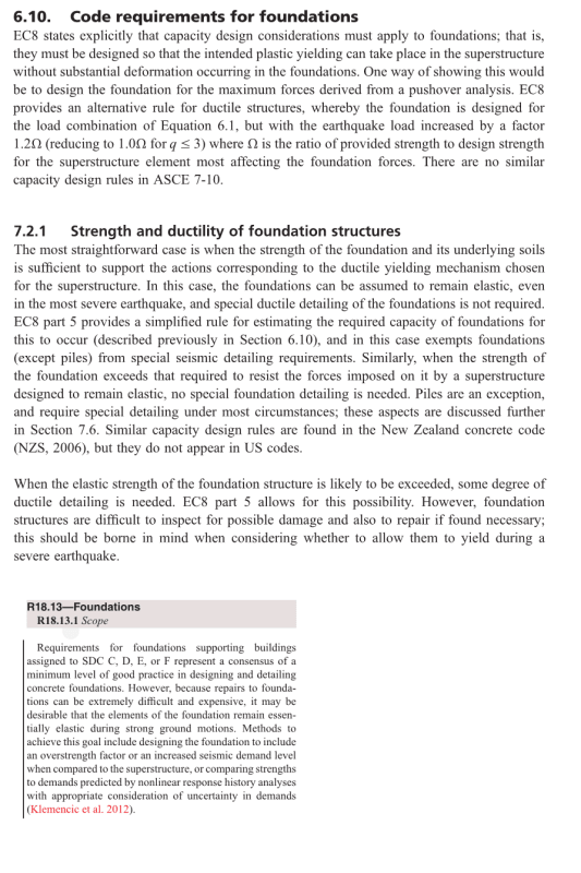
The snips below are from Booth "Earthquake Design Practice for Buildings" and the ACI318-19 commentary. EC8 doesn't seem all that onerous. ACI318 apparently leaves it up to the designer and you could argue that's the intention for Australia given that AS3600's seismic requirements are descended from ACI318.

EQfoundations_qqaypu.png
 
Thank you steveh49 for yor input.

So, if we adopt an approach similar to EC8, unless the whole structure is designed as non ductile (mu=1 Sp=0.77) it seems like the right thing to do is to design the foundation for the full load (design load multiplied by mu/Sp) or do a capacity design based on the capacity of the supported core/shear wall.
Then it would seem sensible to adopt as a factor to the "reduced" design loads the same ones as shown on clause 14.6.6 for the wall shear capacity, i.e. the minimum of 1.6Mu/M* (capacity design, where Mu is the core/shear wall capacity) or mu/Sp (full elastic force).

Would be good to hear from the NZ engineers on this forum what they usually do.
 
Again, the ductility approach is very crude and basic. We're basically reducing all tension steel requirements by 2.6, assuming the bars are all yielding how we expect them to, where we expect them too. Unfortunately, we usually put more steel in than required, we have material reduction factors, and walls may be more or less cracked than we assume, so the actual level of plastic behaviour is probably not even close to what the code prescribes.

Because of this, we need to make sure that no brittle failure occurs first anywhere in the load path, otherwise the structure can't become ductile. So pretty much any shear in the lateral path needs to account for over-strength. Therefore shear in the raft needs to be amplified, and shear in the raft comes from the compression load in the walls/columns.
 
Gishin1 said:
Again, the ductility approach is very crude and basic. We're basically reducing all tension steel requirements by 2.6, assuming the bars are all yielding how we expect them to, where we expect them too. Unfortunately, we usually put more steel in than required, we have material reduction factors, and walls may be more or less cracked than we assume, so the actual level of plastic behaviour is probably not even close to what the code prescribes.

Because of this, we need to make sure that no brittle failure occurs first anywhere in the load path, otherwise the structure can't become ductile. So pretty much any shear in the lateral path needs to account for over-strength. Therefore shear in the raft needs to be amplified, and shear in the raft comes from the compression load in the walls/columns.

Can you further explain this because it is far from clear to me. (Though I'll admit there are big gaps in my knowledge on AS3600.)

If we are reducing our loads in our structure but due to ductility why would they be high on the foundation than they are in the structure. The base shear considered for the structure surely should be the same base shear on my foundation.

 
The base shear in the structure is the same as the base shear on the raft - a horizontal shear (in-plane for the wall). This shear needs to be amplified (CL14.6.6) for the wall design and wall-raft base connection. But the horizontal shear probably doesn't need to be considered in the raft design, as the raft is likely huge compared to the wall (heaps of sliding friction, side face bearing).

The wall vertical compression load acts as vertical shear on the raft, like a big transfer slab. So the vertical shear in the raft needs to be amplified to ensure it doesn't have a brittle failure before it can "flex" and become ductile (raft flexural tension steel yields).

Basically the raft and the wall behaviours are perpendicular to each other. One vertical, one horizontal. So the vertical in-plane loads in the wall act as out of plane flexural loads on the raft.
 
Gishin1
Not just matter of over-design, even just the minimum reinforcment required by 14.6.7 will likely reduce the amount of plastic regions actually forming and increase the overall capacity of the wall substantially.
I agree raft should always be designed with over-strength in shear, however based on those excerpts shown by steveh49 it is clear how any ductile behavior, even flexural, of the foundation is likely to lead to damage in the foundation that cannot be assessed or repaired, therefore it would be good practice to design these elastically or at least capacity-design them so they can develop the flexural capacity of the structure they are supporting.

Can we all agree though that just doing nothing, and blindly design for the reduced loads without thinking through it, as most engineers are still currently doing in Australia, is just wrong?
So basically in Australia we have a situation where on one side the AS committee deosn't spell out every single requirements clearly for engineers, saying that the code is not a seismic design manual and that an engineer needs to have an understanding of seismic engineering in order to apply the code requirement correctly, which would be a perfectly fair point if on the other hand we didn't have universities that do not teach anything about seismic engineering. So how is a greaduate supposed to know what to do? Ask their manager? When their managers most of the times don't know what to do themselves and have been doing it all wrong on their whole career? It doesn't look good at all to be honest and it's a massive risk if, God forbid, a significant earthquake hits one of our big cities. Sorry for the rant.
 
Thanks Gishin1 for the explanation and liogalahad for the rant. The remaining blanks are ones that I need to fill in due to my limited knowledge of AS3600.
(My experience is much more in steel design and industrial structures)

As a somewhat younger engineer I'd agree with liongalahad's rant.
 
I would add that, as far as I know (and please correct me if I'm worng), there's no seismic design manual based on the current Australian standard (AS3600-2018 A2 and AS1170.4-2007 A2), other than some outdated detailing guides or publications.
 
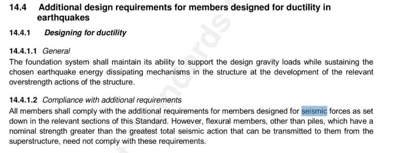
Just to add to the discussion, I just had a look at NZS3101 and the approach seems to be simialr as EC8, with overstrength and capacity design. See below.

Capture_agqti5.jpg


Capture1_fjiv7z.jpg


I have dug out that reference 14.6 mentioned in the commentary, it seems to be a good guidance on this regard, called "Foundations for capacity designed structures", which I still havent read in full. It's a very old document, however the principles should still be valid today. For whoever is interested, it can be downloaded for free here -> [URL unfurl="true"]https://www.researchgate.net/publication/265202154_Foundations_for_capacity_designed_structures[/url]
 
Liongalahad said:
Then it would seem sensible to adopt as a factor to the "reduced" design loads the same ones as shown on clause 14.6.6 for the wall shear capacity, i.e. the minimum of 1.6Mu/M* (capacity design, where Mu is the core/shear wall capacity) or mu/Sp (full elastic force).
Yeah, I thought that would be the order of magnitude, but EC8 only has 1.0-1.2 as the margin compared with 1.6 if we're on the right track in AS3600 terms.

Liongalahad said:
Can we all agree though that just doing nothing, and blindly design for the reduced loads without thinking through it, as most engineers are still currently doing in Australia, is just wrong?
I don't know. I get the impression that's OK by ACI318, provided the ductile detailing is applied. And I think AS3600 would require the same, at least as a vibe.

And that brings me to the question you had about whether there's any book or manual written to Australian rules. I don't think so. The reason I have that Booth book is because it was mentioned in an Australian article as a good EQ design book in the absence of Australian books. So we're in the situation that the AS1170.4 and AS3600 code committees are going it alone without any industry support: universities not teaching the new rules; authors not covering it (AU textbooks are pretty rare anyway); and very little from industry bodies. Engineers are left having to (self) learn EQ design twice, first according to some foreign code which does actually have guidance written, and then mapping that onto the Australian requirements. Doomed to failure.

What's really needed IMO is worked examples. Not examples of isolated elements but for a whole structure that goes through the rules but points out that a decision made for the walls affects the columns and footings etc. And ideally for u=1 vs u=2 vs u=3.
 
Steveh49, I could not agree more with you that we need worked examples of full structures for seismic design based on Australian Standards. It would be a game-changer in the understanding of seismic design for the structural engineering community in Australia.

In regards to the ACI318, I don't see how it allows to do nothing? On the contrary it suggests to use overstrength factors or an increased seismic demand level compared to the superstructure. Unless of course we can assume that in Australia a building design with ductility greater than 1 would always be demolished after a ultimate sesimic event, or course, as inspecting and repairing foundation is nearly impossible.
 
Sorry. I don't know how to quote text so this is directed at several previous messages..

My interpretation of the simplified approach to seismic design in Australia, is that if we ever get the 1/500 or 1/1000 seismic event, you're not repairing the structure afterwards. You're demolishing it. But it doesn't collapse and it provides life safety throughout the event. Remember, with Mu and Sp of 2 & .77, you're pushing the building x2.6 beyond the yield point, so I imagine there's significant damage to the whole structure, far more than any certifier/engineer will want to inspect, repair and re-certify. Foundation cracking is least of your problems, so long as it didn't brittle fail. There's no service earthquakes. The ULS event is extremely rare, but if it occurs, it's catastrophic.

My park and paulay book discusses both elastic and inelastic design for foundations but I haven't gone too far into it, but it's definitely a viable choice to engineers to consider.

I agree with your point about design philosophy in Australia. I've worked for 10 years in some of the biggest firms in the country on some major highrise/low rise structures, and basically none of my seniors had any concept of seismic design. Literally, with high rise, check wind; ignore earthquake. And low rise, check seismic, increase Mu until seismic is less than wind, check wind, ignore seismic. No understanding of what the factors actually mean. No understanding that the building deflects 2.6x or more what etabs says it does. And yes, they all have high-strength,1500x200 section 11 walls and the like.

Most of what I've learnt, and written in these posts is my own research and interpretation of what I think the AS3600 is trying to do. I've got ACI and NZ codes too, but it's tough with different definitions etc and limited construction knowledge/acceptance in Australia of the proper detailing.

The problem with 3600 is that it's a mish-mash of different codes, an amalgamation of BS8110, ACI318, NZ3101, and now the Canadian codes. And everytime they add something new to close a loop holes, they have to patch up all the new contradictions that are introduced. Just look at the last clause in section 11 on restraint ties!! What a mess. Just get rid of section 11 altogether, and rename section 10 "Vertical elements subject to axial and bending loads". Fire design and punching are also very problematic in 3600!

How's that for a rant!
 
Gishin1 said:
The wall vertical compression load acts as vertical shear on the raft, like a big transfer slab. So the vertical shear in the raft needs to be amplified to ensure it doesn't have a brittle failure before it can "flex" and become ductile (raft flexural tension steel yields).
I agree that there should be some amplification here, and that may not have come out in my earlier reply. I do however think that u/Sp is the upper limit rather than minimum requirement, like it is in Clause 14.6.6. And possibly similar to 14.5.2.2(a)(ii) where there's a limit based on double the earthquake force. Hopefully the commentary explains that factor of two.

And the raft shear amplification will depend on whether the raft is elastic capacity-designed (raft shear force based on the wall bending capacity), or ductile-designed (match the raft bending capacity). If the capacity design requirement is similar to EC8, I could easily see the raft ductile design needing higher shear capacity which is counter-intuitive. I definitely leave open the possibility I've misunderstood this.

Liongalahad said:
In regards to the ACI318, I don't see how it allows to do nothing? On the contrary it suggests to use overstrength factors or an increased seismic demand level compared to the superstructure.
That bit is from the ACI commentary rather than the code - I've gone back to edit the earlier post to clarify that. I'm going mainly off the Booth description, which is talking about an older version of the code so maybe a mismatch. But, if ACI recommends capacity design without requiring it, wouldn't the minimum requirement be based on the reduced seismic load similar to what we expect is the usual method here in Australia (rightly or wrongly)?

Gishin1 said:
How's that for a rant!
I feel as though you're saying what Rapt wishes he were allowed to say with some of those talking points.

 
Gishin1 said:
I agree with your point about design philosophy in Australia. I've worked for 10 years in some of the biggest firms in the country on some major highrise/low rise structures, and basically none of my seniors had any concept of seismic design. Literally, with high rise, check wind; ignore earthquake. And low rise, check seismic, increase Mu until seismic is less than wind, check wind, ignore seismic.

So true. I'd also add to the list of this disaster, the lack of 3rd party review requirement on projects (even major ones) so a builder or developer, can simply use the structural engineer that does this rather than using an engineer who know what he's doing because the design becomes too expensive. So the dodgy engineer who doesn't know what he's doing is actually awarded a project over the one who know what he's doing.

steveh49 said:
That bit is from the ACI commentary rather than the code - I've gone back to edit the earlier post to clarify that. I'm going mainly off the Booth description, which is talking about an older version of the code so maybe a mismatch. But, if ACI recommends capacity design without requiring it, wouldn't the minimum requirement be based on the reduced seismic load similar to what we expect is the usual method here in Australia (rightly or wrongly)?

True. It seems to be a mere suggestion rather than a requirement.

Would be also nice to hear from some NZ engineer what is their approach on this.
 
Just wanted to reopen this thread and see what people thinks of stability of a structure, in relation to seismic loads, in particular when dealing with global stability of a structure. I mention this on a previous post on this thread but I would like to expand on this.
In my opinion if we are dealing with stability of a core raft for example, the system has redundancy and alternative loadpaths to reasonably assume that its stability is not necessarily compromised if overturning moments on a core rafts are underestimated - which is definitely be a potential risk when designing a structure and its foundation with a ductility factor mu greater than 1.

A very different scenario however is when we have for example a multistorey building relying on single raft (with or without piles), with all its shear walls and all columns sitting on it, so the the global stability of the building relies on one single structural element (the raft in this case). In my opinion the stability of check on this should be done either with over-strength factors or by multiplying design overturning moments of the whole structure by mu/Sp. Just checking stability based on the reduced loads (multiplied by Sp/mu) make absolute no sense to me. Again, I know I will be having arguments with some of my colleagues regarding this (because the code does not specifically state you have to do this).

Anyone cares to share their thoughts on this?
 
Status
Not open for further replies.

Part and Inventory Search

Sponsor