Wayne _ Lunar
Mechanical
- Jul 10, 2023
- 9
Hi all,
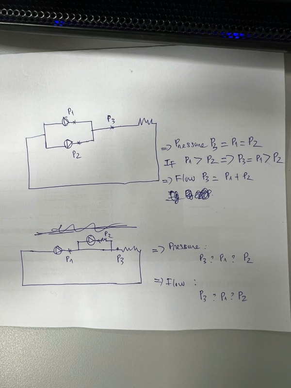
I am working on a pump system based on the 2 configuration shown in the attached sketch. I have a question that I hope you can help clarify.
For Sketch 1, which shows a parallel configuration, I understand that the pressure at Point 3 will match either P1 or P2, depending on which has the higher pressure. The water flow at Point 3 will be the sum of the flows from P1 and P2.
However, for Sketch 2, I am unsure whether it is a parallel or series configuration. My understanding is that it represents a series configuration, where the pressure at Point 3 would be the sum of P1 and P2, and the water flow remains constant throughout.
Could you confirm if this is correct? Additionally, if the water flow or pressure at P2 is greater than P1 in Sketch 2, are there any specific considerations to keep in mind?
Thank you!