Continue to Site

Eng-Tips is the largest engineering community on the Internet

Intelligent Work Forums for Engineering Professionals

  • Congratulations waross on being selected by the Eng-Tips community for having the most helpful posts in the forums last week. Way to Go!

Asking for Parallel or Series Pump Configuration

Wayne _ Lunar

Mechanical
Jul 10, 2023
9
Hi all,

I am working on a pump system based on the 2 configuration shown in the attached sketch. I have a question that I hope you can help clarify.

For Sketch 1, which shows a parallel configuration, I understand that the pressure at Point 3 will match either P1 or P2, depending on which has the higher pressure. The water flow at Point 3 will be the sum of the flows from P1 and P2.

However, for Sketch 2, I am unsure whether it is a parallel or series configuration. My understanding is that it represents a series configuration, where the pressure at Point 3 would be the sum of P1 and P2, and the water flow remains constant throughout.

Could you confirm if this is correct? Additionally, if the water flow or pressure at P2 is greater than P1 in Sketch 2, are there any specific considerations to keep in mind?

Thank you!
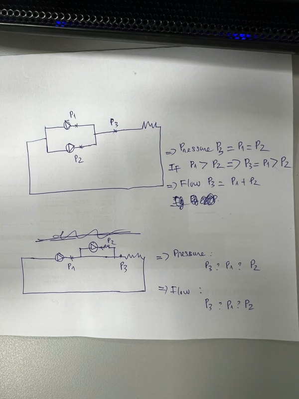
z5955096520984_c713f89498329753a2d76a583bf639cd_uotiyv.jpg
 
Replies continue below

Recommended for you

The bypass is included. For example, the P2 is for Bag water filter.
 
Assuming the pump bypass is always open(as you have shown), the flow will be divided, and the pump P2 head should match the pressure drop across the filter. Pressure at P2 then is greater than P1 by an amount which is the pressure drop across the filter. At connection point P3, the pressure will be almost equal to P2.

But the configuration is not called series configuration, but rather side-stream or bypass filtration.

Engineers, think what we have done to the environment !
 
Sketch 1, P 1, 2 and 3 are essentially the same. If these are centrifugal pumps it's easy for one pump to back out the second it be 90/10 in terms of flow. You need to know the pump curve very well.

All you can say about the second is that the flow will be whatever goes through P1.

P2 will simply run right off the end of the curve and contribute very little pressure increase before it destroys itself.

So p3 will be P1 plus P2, but P2 will be much lower than you think. Unless that non return provided a high level of flow resistance. [pre][/pre]

Remember - More details = better answers
Also: If you get a response it's polite to respond to it.
 
Hi LittleInch

Could you please clarify whether P3, P1, and P2 in Sketch 2 refer to pressure or water flow as you mentioned?


P is pressure.

Q is flow.

Remember - More details = better answers
Also: If you get a response it's polite to respond to it.
 
Sketch 1: P1=P2=P3, Q1+Q2=Q3
Sketch 2: P1=P3, P2 looks like pump 2 discharge pressure: P2=P3+pressure drop across resistance. Q1=Q3, Q2 depends on Pump 2 curve and flow resistance

ETA: Sketch 2 isn't parallel or series with regards to the pumps, this is an example of a primary/secondary arrangement.
 
Sorry, but your sketch of the parallel pumps is fundamentally incorrect. If p1=p2 =p3, the flow =0. No pressure difference = no flow, The same goes for the series pumps.
To do it properly, will require a system of 5 non-linear equations and 5 linear equations, where flows and pressure points are all calculated at once. The pump will be be represented by a curve fit, resulting in gpm = a function of p (pressure).
I recommend the book, "Solving Piping Networks With Your PC", available through Amazon. You will also need a math program, like TK Solver or Mathlab, unless you can solve the equations by hand.
 
Hi all,

I am working on a pump system based on the 2 configuration shown in the attached sketch. I have a question that I hope you can help clarify.

For Sketch 1, which shows a parallel configuration, I understand that the pressure at Point 3 will match either P1 or P2, depending on which has the higher pressure.
Typically , parallel pumps are of same capacity (Same Head & Same Flow), unless you have some special function , which requires more explanation from your side.

The water flow at Point 3 will be the sum of the flows from P1 and P2.
So assuming 2 pumps will run at the same time , and yet they have different heads , this is very unusual.
In parallel configuration , with pumps having same head & flow , when they run together the total pressure is not a simple 2+2=4 . You need to use the pump curves to find out how much the total pressure will be.

A typical pump configuration requires a check valve and a gate valve at the discharge.
Based on the scenario you provided (1 pump has a different head from the other) , when 2 pumps run , the flow will only be the result of the one pump of the higher pressure , as the check valve for the other pump will be closed.


However, for Sketch 2, I am unsure whether it is a parallel or series configuration. My understanding is that it represents a series configuration, where the pressure at Point 3 would be the sum of P1 and P2,
are the 2 pumps running at the same time ? do they have check valves installed at the discharge side ?

and the water flow remains constant throughout.
Again , you want to verify pump curves and generate a new curve .

Could you confirm if this is correct? Additionally, if the water flow or pressure at P2 is greater than P1 in Sketch 2, are there any specific considerations to keep in mind?

Thank you!

I hope this triggers some bulb to maybe re-ask your question with more details.
 

Part and Inventory Search

Sponsor