Eng-Tips is the largest engineering community on the Internet

Intelligent Work Forums for Engineering Professionals

  • Congratulations waross on being selected by the Tek-Tips community for having the most helpful posts in the forums last week. Way to Go!

ASME B16.5 table 8 or 9??

Status
Not open for further replies.

Danlap

Mechanical
Sep 17, 2013
307
0
0
NL
Good day All,

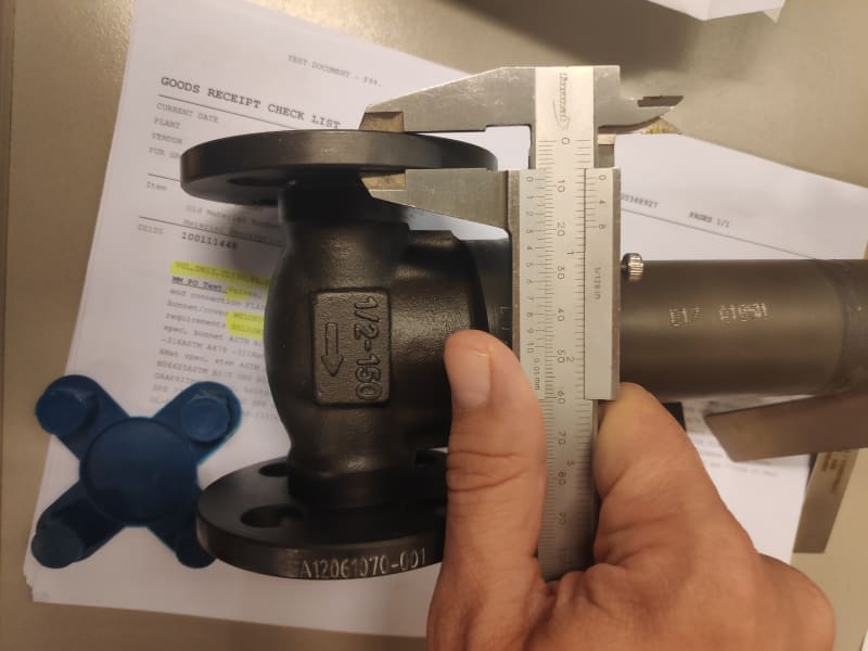
In regards flange thickness (tf as per ASME B16.5), I always refer to Table 8 for class 150#. But without clear explanation, now one of the new vendor had delivered us as per table 9, picture below.
Gate valve 1/2" Class 150#, material is WCB, measured upon arrival tf is 8,6 mm. Whereas table 8 should have minimum of 9.6 mm. And manufacturer without any technical justification refer to table 9 with minimum 8 mm.
flange_150_djhzlx.jpg


I do read the notes on (1),(2) and (4) on both table. It is bit grey area the definition of integrated flange (read: fitting).
Did some simple calculation using flange stress analysis. Gasket used is spiral wound gasket
with minimum 9.6 mm, it would requires 64 Nm to tighten the 4 bolts. Maximum 97 Nm prior jeopardizing the flange ring structure.

With 8.6 mm, it would requires maximum 44 Nm to tighten the bolts, before the integrity of the flange's 'ring' is start to be compromised. This torque value quite on the low side and not as per our flange management standard. I've seen bent spiral wound outer ring upon tightening, but never really see bent flange ring.

I will reject the valve, but aside from above stress calculation, does it really justified with respect to ASME B16.5 for them to use table 9? So far this is the only counter argument from the manufacturer.
Kindly advise,

Thank you in advance,
Regards,
MR

All valves will last for years, except the ones that were poorly manufactured; are still wrongly operated and or were wrongly selected

 
Replies continue below

Recommended for you

Well I think your only defence / point is are they cast integral with the valve or welded afterwards?

If cast integral to the valve then I think table 9 will apply. Note 1 to me is quite clear - it needs to be cast as a single piece to get the benefit of the thinner flange


Remember - More details = better answers
Also: If you get a response it's polite to respond to it.
 
Use table 9. table 8 is incorrect table.

valves are considered fittings, when referring to ASME B16.5 so they refer to the fitting table. Please refer to Table 9 note (1) where it talks about how loose flange is slightly heavier. as the integral design gives the flange strength, so not as thick of a flange is needed for integral flange valves. Do notice that it's only for the very small sizes.

Some can argue, If a welded flange is welded unto a buttweld joint end valve to use the thicker flange. But for integral flange design, use the thinner flange thickness as minimum. However, this is more rare for class 150 valve.

Some history. look at forward section, you will see that all references to valve was removed. so you must now think of things either as a "stand alone flange" or "integral flange on a fitting"


Luke | Valve Hax |
 
ASME B16.34-2017, Valves - Flanged, Threaded, and Welding End, paragraph 6.2.2 states in part, that flanged ends shall be prepared in accordance with ASME B16.5 or ASME B16.47.

Thickness is to be per flanged fittings for Class 150 and 300 valves.
Thickness to be per flanges for Class 600 and higher.

So Table 9 thickness only applies to Class 150 and 300 valves.
 
Thank you all for the explanation.
It is quite interesting that:
- ASME still put smaller sizes on both table 8 (loose flanges) and table 9 (flange fittings), so we have to 'assume' that
- All smaller sizes 150 and 300 valves are cast integral/flange fittings.
- And also that most of its counter piping flanges are as per table 8.

Thanks again,
regards,
MR


All valves will last for years, except the ones that were poorly manufactured; are still wrongly operated and or were wrongly selected

 
I got a Valve Part Drawing for 2" X 150#.

The designer put the Dimension for Flange as 13.9mm + 2mm = 15.9mm.

Whilst i asked him why he did so because the correct thickness shall be 14.3mm + 2mm RF = 16.3mm

But he did respond to me that designers usually did in this way : 14.3mm + 1.6mm = 15.9 (incl RF) hence it is 13.9 mm as Thickness and 2 mm as RF. This is quite confusing as i am still referring to ASME B16.5 & B16.34 but i couldnt find basis of this calculation.

Could someone please elaborate.

Abdullah Ansari
Director - Flowtorq Engineering
 
Most valves supplied would be to ASME B16.5 Table 8 for ASME Class 150.
So in this case you’d come up at a nominal dimension of 9.6mm.

As the is not a fitting shown in the table 9 images it can’t have those applied to it and the flange as per most customer specs is cast or forged integral to the body it would be reasonable to consider it as an integral flange.

Further if you performed and ASME VIII flange calculation on the design based on a typical gasket then you’ll find the fitting thickness’ to be unsuitable in most cases.

The addition of the 2mm raised face in the flat face thickness is a note below the table for the flanges. It allows you to use a single casting with a set thickness and machine the raised face when needed; it also keeps bolt lengths consistent regardless of the joint selected.
 
again, use table 9. table 8 is wrong in this case.

sounds like there is a bunch of new engineer or something, many flanges made to standard dimensions will fail calculation, depending on material. this is because calculation is much more conservative. but have been historically used with no issue, which is why they stayed the way they are in the flange standards.

Luke | Valve Hax |
 
Unfortunately ASME B16.5 draws a line between fitting flanges and flanges.

If you read design standards let’s take API 602 for example they refer, in this case in clause 5.4.4 to flanges not fitting flanges hence table 8 as this is the flange table.

In addition valves are meant to be stronger than pipelines per ASME III NC/ND requires the section modulus of a valve to be 110% of that of the adjacent piping.

Conversely there are some really old ASME code cases referring to both at various points, so it seems as though the specifier has to bear the risks and isn’t a black and white case like most things in this space aren’t.

To be fair it is a moot point as 4”+ the dimensions are the same.

If you put a flange in service that fails calculations then if it leaks you’ll be liable for an repercussions, as you knowingly sold a faulty or sub-standard product.
 
Status
Not open for further replies.
Back
Top