Continue to Site

Eng-Tips is the largest engineering community on the Internet

Intelligent Work Forums for Engineering Professionals

  • Congratulations waross on being selected by the Eng-Tips community for having the most helpful posts in the forums last week. Way to Go!

ASME BPV VIII-1 Studding Outlet Welding Figure

Status
Not open for further replies.

MdRizal

Mechanical
Nov 8, 2020
2
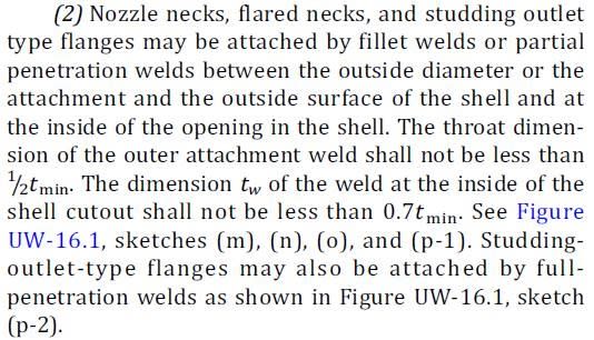
According to Sect VIII-1, Ed 2019 clause UW-16(d)(2) as per attached photo,
the studding outlet may be attached as per Fig UW-16.1(p-1) OR figure UW-16.1(p-2).
UW-16_d_2_cbwebk.jpg


UW-16_1-p-1_2_tvtqit.jpg


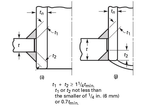
Can we use UW-16.1(i) or UW-16.1(k) for partial penetration?
UW-16_1-i_j_wgqyqr.jpg
 
Replies continue below

Recommended for you

MdRizal, if I understand correctly you propose to insert the studding outlet through the vessel wall, rather than set on the vessel wall.

The former case is governed by UW-16(d)(1), the latter by UW-16(d)(2).

So, yes, design per any of the applicable sketches and associated requirements is permitted.

I am reading from the 2017 Ed, you would need to confirm per 2019 Ed.

Regards,

Mike

The problem with sloppy work is that the supply FAR EXCEEDS the demand
 
Thanks Mike.

This issue have been raised by A.I, they reject our design due to selecting welding figure for studding flange which is not stated in the Code.

A.I said that Studding Flange not similar with Nozzle Neck. Studding Pad not need UG-45

The only clause to comply is UW-16(d)(2). That means only 2 figure is acceptable, here are UW-16.1(p-1) & UW-16.1(p-2) in 2019 ED.
 
MdRizal, although I don't have access to 2019 Ed, I can't really buy into your AIs' argument, and I don't see the relevance of UG-45 to the weld detail.

However: He (or she) is your AI, and you must satisfy him (or her).

Best of luck.


The problem with sloppy work is that the supply FAR EXCEEDS the demand
 
Status
Not open for further replies.

Part and Inventory Search

Sponsor