Continue to Site

Eng-Tips is the largest engineering community on the Internet

Intelligent Work Forums for Engineering Professionals

  • Congratulations KootK on being selected by the Eng-Tips community for having the most helpful posts in the forums last week. Way to Go!

ASME PCC-1 Appendix O: Sfmax (maximum permissible bolt stress prior to flange damage) 2

Status
Not open for further replies.

FPPE

Mechanical
Mar 4, 2022
162
Hi,

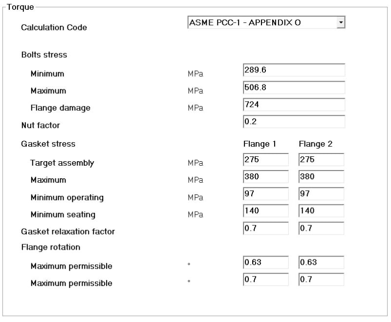
Our software has the following input screen for the calculation according to Appendix O-4 (Joint component approach) Ed. 2022:
App._O_hvccfr.jpg


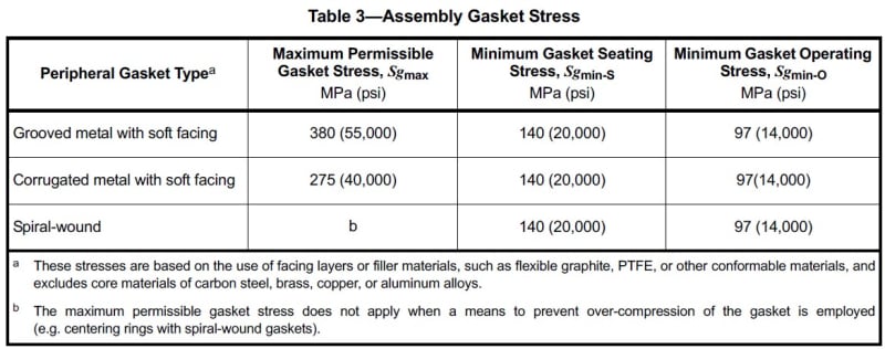
The data entered refer to SA 193 B7 bolts, and a GMGC (Grooved Metal Flexible Graphite Covered) gasket according to API 660 Table 3:
gasket_x2bdza.jpg


According to API 660 7.8.2: "The minimum permissible bolt stress, Sbmin, and the maximum permissible bolt stress, Sbmax, shall be 40 %
and 70 %, respectively, of the listed yield values in the pressure design code at assembly conditions (i.e. ambient temperature)."; SA 193 B7 has a yield of 724 MPa at ambient, so respectively 289.6 and 506.8 MPa.
My doubt concerns the entry 'Flange damage', corresponding to 'Sfmax' on page 67 of ASME PCC-1:2022 (maximum permissible bolt stress prior to flange damage).
Still in the PCC, on page 74 Table O-4.1-2 there are Sfmax values referring to standard flanges in SA 105 (using elastic-plastic FEA).
Could you explain to me a way to find the correct Sfmax value to enter, especially for body flanges of heat exchangers, also by formulas, without the need for FEA?

I doubt that it is necessary to perform an FEA every time a flange joint of a heat exchanger is to be designed, for every flange when Appendix O-4 is required.

Thanks in advance
 
Replies continue below

Recommended for you

You can used the closed form equations instead of FEA. Have a look at WRC 538 for development of the flange limits that Appendix O is based on.
 
Thanks BJI!

Someone could give me some other informations?
 
For heat exchangers with SA-105 flanges designed per Appendix 2 and SA-193 Gr. B7 stud bolts I can tell you that these flanges are frequently torqued in the field to 80%, 90%, and sometimes even 100% of the bolt yield stress without any observable damage to the flanges.

-Christine
 
Thanks Christine!

So for what I’ve understood, it is not a mistake to consider the maximum permissible bolts stress prior flange damage equal to 100% of the bolt stress at ambient temperature, it would results in a thicker flange in order to satisfy all the checks of appendix O-4, right?

I mean, if one or more check doesn’t satisfy the verification, I would manually increase the flange thickness or change the design (number, diameter of bolts, circle diameter) since all checks are satisfied.
 
How do you plan to control the stress on the studs during installation?.

Regards
 
If the strength of the joint is not limited by the flange, rather the bolt strength, then you could go to 100% yield, provided there were suitable (accurate) controls on the measuring the bolt stress, as noted by r6155. Otherwise, you would typically limit it to 70% or 80%, or whatever you can demonstrate is acceptable.

You would still need to know how to determine the flange limit, since there are different allowable limits for flange assembly loads vs. design loads. It won't result in a thicker flange unless you were somehow feeding this back into the design iterations. I wouldn't be designing the flange for 100% of the available bolt load, if that was the intention (i.e. per the note at the end of ASME VIII-1 2-5(e)).
 
Hello, someone could explain to me how to apply the equation of WRC 538 in order to determine the Sfmax value?
Thanks in advance
 
FPPE,

Did you go through Para O-5.2? It gives you some allowance and direction for using different gasket and flange materials using the values from O-1 to O-7. I would say, you can with confidence use this criteria [Sfmax (From O Tables)x(SYFlange/SY105)] for Group 1.1 materials to calculate Sfmax for the new flange material.
What’s your new flange material? If it falls in another group, you may not use the above criteria if the difference in P-T rating is wide. Then Appendix -2/WRC 538 would be your direction.
On your last question, the WRC 538 equations are all based on Sec VIII Div 1 appendix-2. In fact, WRC has added few more stress combinations to determine Sfmax. The assembly bolt stress, Sfmax will be the value when the allowable assembly stress in one of the given seven conditions will exceed.
The assembly bolt stresses are a function of bolt load and design pressure. The design pressure being constant in our case, it’s obvious that Sfmax will be a function of Bolt Load. It's a bit complex but complete understanding of Appendix -2 is required to carry out this exercise.

GDD
Canada
 
have you asked the original question to the owner of the software you're using?
the author of WRC538 owns an engineering consultancy and wrote a Sfmax calculation software available for purchase from the consultancy website. However, I strongly recommend the training before you try and use it if you don't have a sound understanding of the asme-viii-1-app2 calc method.
I concur with the other comments above - you're better off interpolating the Sfmax from PCC1 app. O tables if you have equivalent materials (E and poissons ratio) and comparable dimensions to the flanges in the tables. Note that the operating temperature is another consideration because this will reduce the flange yield strength and thus the Sfmax load.
 
If you can perform an ASME VIII-1 Appendix 2 calculation then you should be able to perform the WRC 538 calculation. Why not simply create a spreadsheet?

I believe there is a simple WRC538 calculation available for free online, the licenced software is more comprehensive. I would still recommend making your own but here is the link:
 
Status
Not open for further replies.

Part and Inventory Search

Sponsor