Eng-Tips is the largest engineering community on the Internet

Intelligent Work Forums for Engineering Professionals

  • Congratulations MintJulep on being selected by the Eng-Tips community for having the most helpful posts in the forums last week. Way to Go!

ASME PCC-2 Fillet Welded Patch Repair

Status
Not open for further replies.

JAR10

Mechanical
Mar 19, 2019
6
Hi everyone,

I am looking at specifying a fillet welded patch plate repair to ASME PCC-2. I have demonstrated the proposed patch plate thickness to meet the requirements of the original vessel design code, and I have sized the attachment welds to Equation (4) within Article 212 of PCC-2. These steps so far are producing reasonable numbers. Where I am struggling however is trying to satisfy Equation (5) within PCC-2.

I can see what this calculation is doing - using the eccentricity between the parent plate and the patch plate to quantify a bending stress, and then adding this to the imposed hoop stress. However, I have the below query:

1) The calculated stress is described as a weld stress. However, weld size is not a calculation input, but the patch plate thickness, T, is. At first I thought the code is making an assumption that the fillet weld leg length will equal patch plate thickness. But I'm not sure this is the case. Does anyone have experience of using this equation and insight on to whether this assumption is correct, or if I am misinterpreting the code?

Many thanks in advance for any assistance on this.
 
Replies continue below

Recommended for you

Formula (5) implies that the thickness of the patch must be greater than the thickness of the shell.

Regards
 
Hi r6155,

Thanks for the reply. I understand the thickness requirements for the patch plate will be greater than those for the shell due to the eccentricity loading check.

Looking further into Equation (5) I have summarised my thoughts below:

I think the equation does make an assumption that the fillet weld size will match the patch plate thickness. The calculation is determining a weld stress (Sw), therefore it should be the weld dimensions we are interested in. However the input into Equation (5) is patch plate thickness, not weld size which at first seemed strange to me. I would expect a weld stress calculation to consider the weld throat thickness.

But further review shows that equation (5) sums a hoop stress with a bending stress.

The bending stress is the second part of the equation and is based on M/Z. M is equal to the hoop force (PDb/2) multiplied by the eccentricity (e). Z is equal to bt^2/6, where t is the weld throat thickness and b = the weld length.

This gives stress = (PDbe/2) / (bt^2/6) which can be re-arranged to give 6PDe/2t^2. As there will be a weld on both sides of the patch this can be halved to give 3Pde/2t^2. This now looks very similar to the second part of Equation (5). The difference being Equation (5) contains T^2 instead of 2t^2 where T is patch plate thickness and t weld throat thickness. However, due to the relationship between weld leg length and throat thickness, T^2 will always equal 2t^2 if the weld leg length equals the patch plate thickness.

So, I think I have answered my own question regarding the code assumption that fillet weld size will equal the patch plate thickness. But, it would be great for a second opinion on this.

Regards,

JAR10
 
The pressure vessel is not just calculations.
Have you considered the manufacturing, inspection and testing requirements for this design?

Regards
 
Hi r6155,

Yes these aspects have been considered as part of the repair specification, but they don't relate to my query in the OP.

Thanks,

JAR10
 
Sorry, I can't be your checker free. Contact your boss.
You are unsure with your calculation?

Regards
 
r6155,

With all due respect, I haven't asked anyone to check my work, and I wouldn't expect any forum members to provide free consultancy. This is a debate on what the code is doing, and at no point have I asked anyone to check my actual calculations relating to the project I am working on. This will be done by a colleague. I shared my derivation of Equation (5) from Article 212 as I thought it may be useful to others.

I am confidant I have answered my own question, but I have thrown it open to the board incase anyone else has a differing opinion or has anything else to add to the topic.

Regards,

JAR10

 
Hi, My query

It is logical for me to think from this article that the pressure "P" to be used is the residual pressure, that is the pressure the patch should only withstand due to lack of thickness of the equipment or pipe, and not the total design pressure.

I will appreciate your comments.

Regards,
CMP.
CHILE
 
Reinforcing plates and saddles of nozzles attached
to the outside of a vessel shall be provided with at least
one vent hole……

See UG-37

Regards


I understand that if the patch is installed due to a leak, the pressure used for calculating the patch should be equal to the design pressure, on the other hand, if the patch is installed to cover a local thin area, the pressure for calculating this should be a pressure lower than the design pressure, it would correspond to the residual pressure between the design pressure and the pressure that can withstand the local thin area plus the expected corrosion.

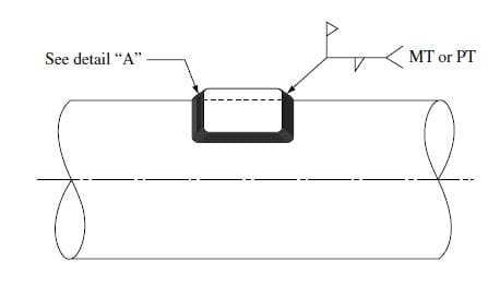
lap_patch_rog7rp.jpg


I will appreciate your comments.

Regards,
CMP.
CHILE
 
Leaks shall be sealed.
Patch plate shall be leak tested.

Regards
 
Hi CMaldini,

In my experience, I have always designed patch plates considering the design pressure. Even if an LTA remains, and the patch plate is not covering a hole, I always take this approach in case the thinning mechanism was to continue. This could certainly be the case for loss initiating from the inside.

Regards,

JAR10
 
I give an example:

Data:
Shell Equipment (Asme VIII Div 1)
Pd: 350 psig (24.12 bar)
Td: 225 °C (437 °F)
Shell Material: SA-516 70
E: 1
thk. nominal: 21 mm
corrosion allow.: 3 mm
min. thk. mesured: 16.51 mm (local thin area)

Calculate min. thk. and MAWP, Section VIII, Division 1, 2013:

local thin area -> CA=21mm-16.5mm+3mm = 7.5mm.

Min. thk. shell, with local thin area per per Appendix 1-1 (a)(1)
ASME Code, Section VIII, Division 1, 2013, with local thin area ->
t=16.8 mm, MAWP=279 psi.

Calculate ART 212 ASME PCC-2:
(1) for Ppatch= Pd, according to ART 212 ASME PCC-2 the T= 63 mm
(thk. patch) and w min= 63 mm (min. weld leg), too thick.

(2) for Ppatch= Pd-MAWP= 71 psi, according to ART 212 ASME PCC-2, T=18 mm (thk. patch) and w min= 16 mm (min. weld leg). I find these values ​​to be more reasonable..

I appreciate your comments

CMP.
 
I would insert the plate with a butt weld and a root tig weld

luis
 
Also consider adjust the weld joint efficiency factor, E (0,85 to 1), by conducting additional examination.
I don`t know the original factor E.

Regards
 
CMaldini,

I'm not really sure of the validity of your approach, as once patched it becomes difficult to monitor the thickness of the LTA region you will have over plated. In my experience for higher pressures, the PCC-2 patch plate requirements can be impractical due to the eccentricity check. This is where other methods such as an insert plate or a patch plate with plug welds may be needed.

Regards,

JAR10
 
Status
Not open for further replies.

Part and Inventory Search

Sponsor