Continue to Site

Eng-Tips is the largest engineering community on the Internet

Intelligent Work Forums for Engineering Professionals

  • Congratulations Danlap on being selected by the Eng-Tips community for having the most helpful posts in the forums last week. Way to Go!

ASME VIII-1 guidance on threaded end cap

XL83NL

Mechanical
Mar 3, 2011
3,077
Cant get my head around this, as I think Ive done it before under ASME, but cant recall how.

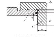
Im looking for some guidance in VIII-1 on a (large, 4") threaded end cap. The threads for the cap mate with the pressure shell. Below is a picture of the situation. Item 2 is the cap, with straight threads, that mates with a pressurized shell (item 1) having the same straight threads, on the outside.

My sutiation is slightly different (a.o. I have an insert between 1 and 2, holding the O-ring), but essentially works the same. This config isn't listed under UG-34. Appendix Y doesn't. I found a possibility under an EN standard for gas loaded accumulators, but Id like to stick with ASME all the way to keep things clear.

Any through if something similar is addressed somewhere in VIII-?
1739298002668.png
 
Replies continue below

Recommended for you

Both UG-34(d) (4) and (12) have the description for "screwed over the end of the vessel" which would represent your figure.
 
Man...this is dicey. Any reason you can't just make this a flange joint?
 
No problem, the O'Ring does all the work.
 
Both UG-34(d) (4) and (12) have the description for "screwed over the end of the vessel" which would represent your figure.
Not really. I haven’t described my question properly. I’m looking for a way, if any, in ASME how to calculate the thickness of the shell to accommodate both for internal and straight thread (allowance).
Man...this is dicey. Any reason you can't just make this a flange joint?
No sorry, this needs to be as it’s now. In the past we have done similar things with pipe machined from bar but it’s likely I need standard pipe (5” XXS), which gives me little extra margin (that we normally account for by just machining a custom thicker hub with excess thickness).
No problem, the O'Ring does all the work.
Sorry but that’s not my question. I’m concerned with the shell end which needs thickness for interlaced pressure and thickness for straight threads (ISO 228-1).


Ps; does anyone know how I can edit my first post/question? There’s no edit button
 
See UG-31
(2) Where ends are threaded, additional wall thickness is to be provided in the amount of 0.8/n in.(20/n mm) [where n equals the number of threads per inch (25.4 mm)]
 
See UG-31
(2) Where ends are threaded, additional wall thickness is to be provided in the amount of 0.8/n in.(20/n mm) [where n equals the number of threads per inch (25.4 mm)]
Yes, exactly, that seems familiar (for this example). Does it apply to straight threads though? That would definitely make it work.
Since we (can) also use this threaded end cap as an inspection opening, I can justify it under UG-46 (i). But other than that, VIII-1 is quite silent on straight threads
 
Straight thread is mentioned in several places: UG-37(g), UG-43(e)...etc, etc.
Use UG-46(i) at your convenience.
 
Right, but threads mentioned in U-3 are tapered only. Suggesting straight threads, like in the sections mentioned, are only for the specific reasons per those sections.
 
Thanks. I think I got it covered now.
(PS: U-2(g) was always an escape - employing EN 14359, from which the sketch of my original post is taken from)
 

Part and Inventory Search

Sponsor