Eng-Tips is the largest engineering community on the Internet

Intelligent Work Forums for Engineering Professionals

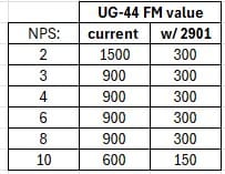
ASME VIII UG-44(b) 4

Status
Not open for further replies.

JoeSeag

Mechanical
Jan 24, 2024
12
0
0
US
I've seen rumors floating around for a few years that this section is being potentially revised/removed in future editions. Anyone have insight? In any case, I've followed this discussion for years and still haven't had much success resolving the intent, what to do with the "may" statement, and how to best implement it in the ever increasingly tight project schedules. We provide external nozzle load allowable charts to the PV vendor early on for their design of the shell/nozzle junction. However, as many have stated prior, using these same values for UG-44b would significantly increase flange ratings by many steps. Waiting for the piping stress analysis to be performed would result in many changes in PV design without disrupting schedules. What are folks doing these days? Uprating their flanges considerably? Delaying schedules with flange changes after pipe stress? Or something I've not thought of perhaps? Much appreciation for input!​
 
Replies continue below

Recommended for you

UG-44(b) will, unfortunately, not be updated in the near term.

However, a revision to Code Case 2901 has been Board approved and will be published imminently. The revised Code Case provides substantial relief to the Fm factors.
 
Thanks for that input. Do you mind making sure I understand this appropriately? Here's how I understanding it:

Code case 2901 was the source of this topic originally, then it was moved into the mandatory section of the VIII-1 code. Now a revision to that original code case 2901 will be made with a set of Fm factors that we would use in lieu of those shown in VIII-1 table UG-44-1.

Does that sound right? If so, it appears "substantial relief" to Fm factors would potentially eliminate much of these concerns above.

Related to this topic, I have been working with Hexagon via their "ideas" board to try to incorporate UG-44b flange leakage check within the static analysis options.
 
Great! These Fm values are indeed substantial relief. My test model shows before vs after flange rating selection as a result:

Screenshot_2024-03-04_121045_m7iqg1.jpg
 
yuun - good catch.

Code Case 2901-1 has been officially published now. There are three typos (that I have seen) in the officially-published version - the first is the one that yuun caught. The next is that the NPS 3/4 (DN 20) size reads as NPS 1/4 (DN 20). The third typo is that the NPS 3/4 (DN 20) Class 300 F[sub]M[/sub] factor should be 9.1, and not 19.1.
 
Same paper - just the full data set (not the scaled down data set that Dr. Brown originally proposed in his paper). The data is in the paper - I received that actual numbers from Dr. Brown himself for use in the updated Code Case.
 
Does anyone know if there is a plan to include guidance in code on method to use for Slip-On flanges with external piping loads? In my company we extensively use Slip-On Flanges on our vessels. I am not sure what method I should use to address piping loads for flange design. Is it OK to use the code method even though the code explicitly states that the method is for Weld Neck Flanges? Kellogg Equivalent Pressure method seems very conservative and for example sometimes pushes the flanges on our lower pressure vessel from Cl. 150 to Cl. 300 even though the piping specification connecting to these nozzles lists cl. 150 Flanges are adequate. Is any of the methods listed in this article preferred for Slip-on flanges? Any guidance on this will be greatly appreciated. Thank you.
 
@TGS4 Thank you for your response.

In code case 2901, Fm value table note b reads "The designer should consider reducing the allowable factor if the loading is primarily sustained in nature, and the bolted flange joint operates at a temperature where gasket creep/relaxation will be significant [typically above 450°F (232°C) metal temperature".

1) Fm values in code case 2901 are same as mentioned in paper PVP2013-97814. In paper Dr. Brown has mentioned to divide Fm values by 2 in case of sustained loads. Since code case is silent on the factor to be used, can we divide Fm value by 2 and use?

2) For effect of creep and relaxation above 232 Degree temperature, is there any guidance available to reduce Fm values?

3) in paper PVP2013-97814, Dr Brown has referenced "Brown, W., 1993, “Design and Behavior of Bolted Joints” 3rd International Conference on Fluid Sealing, CETIM, Nantes, France, pp. 111-121" for the mechanical interaction effects. I tried searching this paper on internet but could not get my hands on it. It would be of great help if someone can share.
 
1) That would be up to your engineering judgement. The Code is silent on this issue.

2) No guidance is provided. Use your engineering judgement.

3) You could always contact Dr. Brown directly. Here is his contact info.
 
Hello, I'm trying to understand where I can get a copy of a finalized released version of Code Case 2901-1 with the published Fm values shown in the redlined picture. Reason being is that these values are much more solid when using the calculation. Is it acceptable to use these Fm values rather than the ones posted in ASME SECTION 8 DIV I UG-44 Table 1? If so, ho wcould I state that these are acceptable values to use, and have they been approved by the ASME committee for use?
 
The revised Code Case was published in the Code Case Supplement 4.

Regarding the “acceptability” of the values - that’s between you and your jurisdiction/client, since the use of Code Cases are not mandated by the Code.
 
Status
Not open for further replies.
Back
Top