appst8design
Nuclear
We are having an internal disagreement at work on the correct way to dimension an ASME Y14_5 2009 drawing. Looking to see if there is a standard out there that I'm not able to find or how other people would approach dimensioning this part.
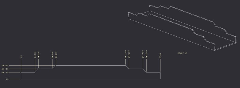
In the example(attached picture) we have a cut that runs through the entire part
The disagreement is on how we utilize multipliers with linear/ordinate dimensions. Some people are of the opinion you add multipliers for features shown in the view as well as features that are inline behind the view. So if you have a cut that goes through, they are of the opinion you would add a 2X to every dimension to account for the edge behind (see attach picture). My problem with this is it clutters the drawing with unneeded multiplier notes. Other people in the office are of the opinion if it's an inline cut it doesn't receive a multiplier, it only receives a multiplier if it aligns to another edge/feature in the view you're dimensioning (I'll follow up with another picture).
How would you guys use multipliers for linear/ordinate dimensions on this part? Which do feel is correct?

