Eng-Tips is the largest engineering community on the Internet

Intelligent Work Forums for Engineering Professionals

  • Congratulations waross on being selected by the Tek-Tips community for having the most helpful posts in the forums last week. Way to Go!

Assembly workbench: only H-V axis visible 3

Status
Not open for further replies.

iamnotsure

Military
Aug 23, 2019
12
0
0
CH
Bonjour,

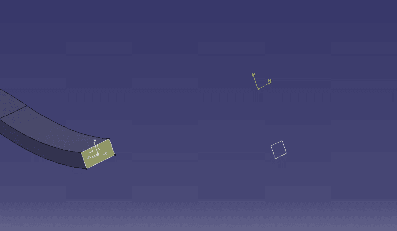
During work in assembly design, sketch edges are not visible. Displayed are only V-H axis. I would like to use sketch edges as a spline reference.
Product:
1_gewdw4.png


"Inside" a sketch:
2_mkpncm.png


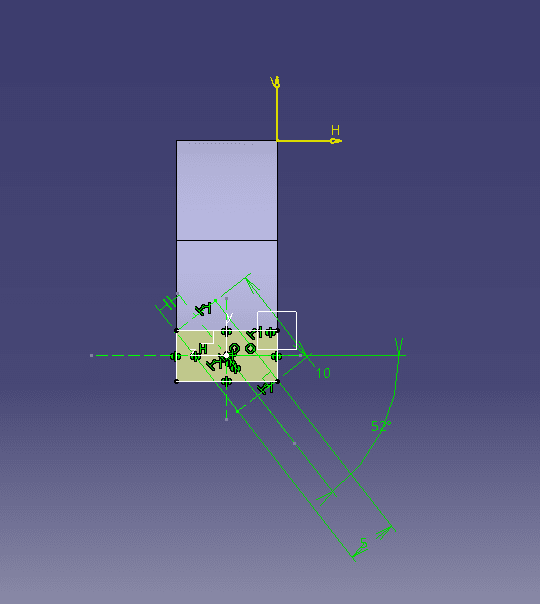
It is so irritating, silly problem, spend half an hour looking for an answer.
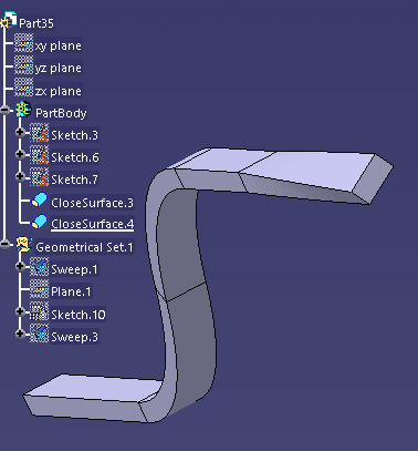
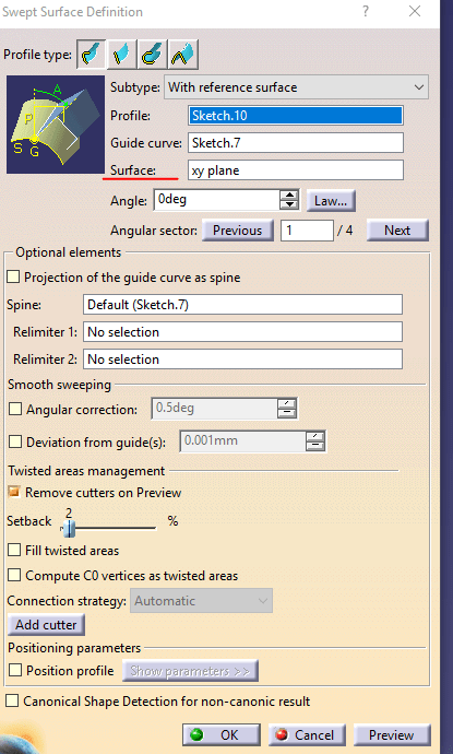
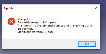
By the way, any more convenient way to twist the part (on full length or partially)? Currently, I am using multi-sections solid (3 sketches, 4 splines as guides) to twist a rectangular shaped bar for a certain degree, it is a bit time consuming.
 
Replies continue below

Recommended for you

but both your pics show the same geometry (but in different projections-- I see the V-H axis, but also the rectangle and the squire)?

regards,
LWolf
 
The reason you can't see any of the sketch items unless you are editing the sketch is because all of the sketch elements are construction geometry (they show up as dashed lines instead of solid, and points are dots instead of crosses). If you want to use any of the lines, points, etc outside of the sketch, they cannot be construction geometry.
 
Dear LWof,

Merci, it's such a cool tool! Love the degree of angle control provided by the law button.
So I have managed to make solid from two closed, swept surfaces:
yeah_aydnkw.png


As I understand, those two CloseSurfaces are one solid PartBody now? I don't have to make some strange boolean or joining operations.

I also do not fully understand the effect of "Surface" reference (from geometrical point of view).
swe_yzk822.png


When I am choosing the same plane where a profile was sketched, error:
error_e6p2xc.png


When I am choosing one of two other original part planes, the effect is the same, I cannot get what information we are giving by choosing reference surface.


Merci beaucoup again. Anyhow, the first problem (sketch edges not visible in Part Design workbench) is still not solved :D
 
reference surface/plane is where you measure the angle from. Try this: Choose linear sweep with reference surface. You have your guide curve, and as your profile make a line which is normal to the guide curve (starting at one of the guide curve's ends). say your guide curve is in the xy-plane--choose xy-plane as support. in Law for the angle, choose linear type, start 0; end 3600 :) see what happens :)O

regards,
LWolf
 
Status
Not open for further replies.
Back
Top