Continue to Site

Eng-Tips is the largest engineering community on the Internet

Intelligent Work Forums for Engineering Professionals

  • Congratulations KootK on being selected by the Eng-Tips community for having the most helpful posts in the forums last week. Way to Go!

Assessment of crane rail system - fatigue 2

Status
Not open for further replies.

m_struct

Structural
Nov 11, 2020
64
A client has a 25 year steel portal frame warehouse with an existing crane rails and an existing 3 ton gantry crane in use. He would like to add two more 3 ton gantry cranes and says that is what the building use to have. That was a couple owners ago.

The warehouse is approximately 32m (110 ft) wide with central row of columns - 2 bays in the long direction. He would like to reuse the existing crane rails. Crane rails are continuous UB's with channel fixed to top flange and supported at each column on a steel corbel.

With such a structure, how is fatigue taken into account? As the building is 25 years old, and we currently do not have documentation (or an estimate) of how many cycles this has seen, how would you approach the fatigue part?

 
Replies continue below

Recommended for you

Without a loading history, it's difficult to determine. I'm curious to see what NDT is recommended. Seeing your name, I was thinking of changing my name to d_struct. [lol]

So strange to see the singularity approaching while the entire planet is rapidly turning into a hellscape. -John Coates

-Dik
 
you could ask some expert in FEM-Ansys to model your girder-connections (points of stress concentration) it will gives you a clear (No of years left), also they will recommend the correct (economic & effective) solution
 
sure you can model the structure but without a service history or a typical loading then you're just guessing. Sure you can define a typical load of 60% limit, or fuss it and say 90% cycles at 50% limit and 10% at 80% or countless variations thereof.

what is the condition of the existing crane ? has it been well maintained ? could you do a HFEC inspection ? (yes, overkill, but even this is unlikely to detect small fatigue flaws, like what I expect you may have.

Do you have any idea of the internal limit stresses ? if low then "infinite" life.

How redundant is the structure ? If one piece fails, does the house of cards come falling down ??

What does your local code (for overhead devices) have to say ?

"Hoffen wir mal, dass alles gut geht !"
General Paulus, Nov 1942, outside Stalingrad after the launch of Operation Uranus.
 
FEM-ANSYS is well set to present the accumulative fatigue life (with multiple factors)
these factors, could be change according to your best of knowing [history of loadings]
ANSYS Fatigue-module was invented for car-parts under sever repeated loading (including thermal effects)
add additional life to your structure through ;
-adding web stiffeners
-adding lateral bracing to top/bot flanges or web plates of carne-beam
-adding web-side plate [to increase the bearing capacity] of carne-beam
-adding curtailment plates to top/bot flanges [to increase the bearing capacity] of carne-beam
-drilling holes @ web to reduce stress concentration / prevent further crack propagation

it is just an opinion, a start point to OP so he could make the right engineering judgement
[if you couldn't make it simple, it will become more complex]

the process is similar to steel Bridge rehabilitation
 
again you can model the structure all you want but without a sensible spectrum you won't get sensible results ... whatever s/ware you use.

GIGO.

"Hoffen wir mal, dass alles gut geht !"
General Paulus, Nov 1942, outside Stalingrad after the launch of Operation Uranus.
 
I think your duty is to evaluate the crane runway girders and runway supporting structures for the additional cranes, which could be working bumper to bumper and causes the elevated stress range/reversal that would shorten the runway's service life. Since this is an old runway, you will have to estimate the reasonable loading cycles it has experienced. I suggest searching AISC, AIST, and CMAA (Crane Manufacturer Association of America)for crane runway design information.

Though crane rail is essentially a part of the runway girder/beam, however, depending on how it was attached, and the spacing of the attachment, the analysis can be quite involved. Therefore, I'll leave it to a more experienced/ competent person to handle it. Here is an old article about the design of crane runway structures for your info. PLease pay attention to CH3 and beyond. Link
 
Can you get the client to agree that none of the cranes can be in the same bay at the same time? If so, you wouldn't be adding any additional load to the beams although you could be adding more fatigue cycles.
Having cranes not be allowed to be in the same bay at the same time is common. They have fancy laser equipment to prevent them from getting too close but I've also heard of just welding a bay long beam to the end trucks of cranes on one side that ride on the crane rail with new wheels and a crane stop at the end of the beam.

Also, it should be straightforward to check the existing crane beams for loading, deflection and fatigue. There are probably some exceptions but every crane beam design I've seen has been controlled by deflection. This should give you extra fatigue capacity. For example, you could run the fatigue formulas for the various components and find the that maximum stress range is, for example, 16 ksi. Then if you check what the actual stress on the beams are and find they only get to 8 ksi, you at least have some judgement that they should have some additional life in them beyond the 25 years of service.

Alternately, if they check to a stress range that's close to or over the fatigue limit, then you've also given yourself a data point to help make your decision and maybe to help the client make the right decision to replace them.

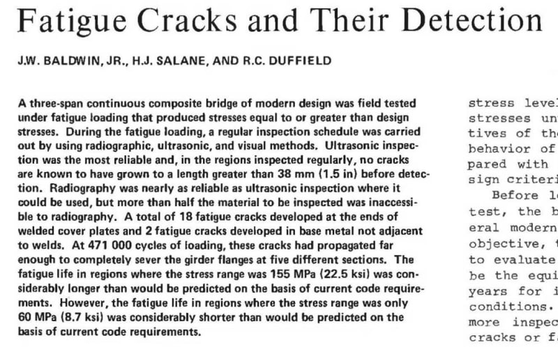
You could also get the beams tested for fatigue cracks with ultrasonic testing. I've only heard of this being done on welds but a quick google search brings up examples of where bridges were tested for fatigue cracks at weld and at base metal not adjacent to welds.

Fatigue_Cracks_g27nr6.jpg
 

Without a detailed loading history, this is a 'fools errand'. I don't think it can be done.

I was hoping that someone could recomment an NDT method that could be used for determining this... [pipe]

So strange to see the singularity approaching while the entire planet is rapidly turning into a hellscape. -John Coates

-Dik
 
on the other hand, you can make a (presumably) conservative assumption, say 80% (100% ?) limit load, moving along the full span, X times per day.

But this is just the beginning. Then you need to assess points of stress and maybe there are consistencies between spans. In the luckiest of worlds you'll be able to say either this point is the most critical, or that this point is typical of several spans. In other worlds you'll have several points to analyze. Now you can do a fatigue analysis. But something you can do, with several points, is show that cracks are unlikely to develop in some places and others take longer to initiate than your critical site(s). So if it onerous to inspect the whole damn thing, you have reasoning for saying we need to be most concerned about these places, less concerned here, and really not concerned here (yes, I know, you should inspect everywhere, for accidently damage or corrosion).

But fatigue only gives you the "safe life" and tells you nothing of growing flaws, or how to inspect the structure. For that you need damage tolerance ... how extra level of "fatigue" analysis ! And I'm not saying you Have to or Need to, only that is an analytical basis for an inspection program. Other methodologies exist, whatever is commonplace in your business is an excellent way to start.

Of course you can always "wing it". We'll do a visual inspection every year, or a HFEC (or ultrasound) every two years, or whatever. Only these programs are not analytically based, but they may be consistent with typical practice in your business. It could be reasonably impossible to get even a halfway descent service history or typical loading, and it could be that cranes are designed to such low stress levels that fatigue is not really a driver of failures.

"Hoffen wir mal, dass alles gut geht !"
General Paulus, Nov 1942, outside Stalingrad after the launch of Operation Uranus.
 
There are so many unknown issues... can the crane be overloaded or is there something that prevents it? What sort of abuse has the crane suffered? Was there any maintenance ever done? Were there any improper repairs? If more than one crane, how were they operated to effect what kind of loading on the crane beam? Just too many questions... [pipe]

So strange to see the singularity approaching while the entire planet is rapidly turning into a hellscape. -John Coates

-Dik
 
Can eddy current and ultrasound reliably determine fatigue life? Just trying to learn here... [ponder]

So strange to see the singularity approaching while the entire planet is rapidly turning into a hellscape. -John Coates

-Dik
 
@dik,

Crane rail and girder are inspected periodically to spot potential problems. As opposed to the crane girders, the defective rail segments are more likely to be replaced before it runs out of their service life, because, compared to all other components, the rail is cheap and easier to replace without requiring a long period of plant shut-down. A worn, torn, or misaligned, rail can cause severe damage to the crane wheel, which is much more expensive to replace, and usually will idle the crane for a longer period due to a lack of spare parts.
 
"Can eddy current and ultrasound reliably determine fatigue life?" ... no, but they can detect flaws/cracks. This is not fatigue analysis.

Fatigue is focused on crack initiation, typically orders of magnitude longer than detectable crack life. Fatigue doesn't consider flaw growth, in fatigue the part is intact on minute, and broken the next. Fatigue gives you a safe operating life.

Damage tolerance is the analysis of flaws growing into cracks. You can calculate how long a crack will take to grow from detectable size (depending on your inspection method) to critical size, and so how to inspect to "guarantee" safety..

before damage tolerance we had no analytical method for determining inspection programs. We used experience and judgement ... often well, sometimes poorly.

And corrosion is a whole different problem.

"Hoffen wir mal, dass alles gut geht !"
General Paulus, Nov 1942, outside Stalingrad after the launch of Operation Uranus.
 
thanks le and rb...

So strange to see the singularity approaching while the entire planet is rapidly turning into a hellscape. -John Coates

-Dik
 
Thank you for all the responses. In terms of inspections, what if a testing agency does a visual inspection of welds, followed by NDT of any welds in question and spot checks those in high stress regions?
NDS could be magnetic particle inspections on fillet welds and ultrasonic on full penetration splices at shown attached. If the service life is say 25 years, what is done at the 25 year mark?
 
 https://files.engineering.com/getfile.aspx?folder=bc3d567c-f454-47be-865d-7747c77aee3c&file=Crane_Runway_Inspections.PNG
"what is done at the 25 year mark?" ... the same inspection (as for original production) ? ultrasound, HFEC, LPI, MPI, ...

I have worked with a plane that has a welded landing gear. Repetitive inspection and grinding out flaws and re-welding to keep the structure sound.

"Hoffen wir mal, dass alles gut geht !"
General Paulus, Nov 1942, outside Stalingrad after the launch of Operation Uranus.
 
Status
Not open for further replies.

Part and Inventory Search

Sponsor