Continue to Site

Eng-Tips is the largest engineering community on the Internet

Intelligent Work Forums for Engineering Professionals

  • Congratulations KootK on being selected by the Eng-Tips community for having the most helpful posts in the forums last week. Way to Go!

At what pressure do I get full flow? 6

Status
Not open for further replies.

PNachtwey

Electrical
Oct 9, 2004
772
Backgound,
I have a small eaton-vickers pump that looks almost like this only mine is green.
It has a 5 HP motor driving a 5 gpm pump at full flow.
We no problems with setting the system pressure at about 1500 psi when there is no flow. We can't adjust it much higher because the 5HP motor is limited.
The pump should provide no flow at 1500 psi.
The question I have is at what pressure do I get full flow?
It seems to me this is a function of the spring. Adjust the spring in and out adjust a proportional band where the flow is proportional to the pressure drop from 1500 psi. However, there is no way to know how far the pressure must drop to get the full 5 gpm from the pump. It seems to me that this would be a function of the spring constant. A stiffer spring would more cause the port to the swash plate to open up more with a smaller pressure drop. This essentially is changing the proportional band of the pump.

Are there specifications for this?
Are there specifications for how fast the swash plate moves?
Is it possible to replace the spring in the compensator?
As a controls person this seems simple but crude.
BTW, know the flow because I can measure the speed of the piston and know the areas of the piston but I am looking for a general case.


Peter Nachtwey
Delta Computer Systems
 
Replies continue below

Recommended for you

In mobile hydraulics, such as medium to large size excavators there is a lot of torque curve matching going on (using electronics) to get the absolute most hydraulic power out of the machine and also optimisation to get the absolute lowest fuel consumption for a certain job. CTL forestry machines is another application where both performance and efficiency is high up on the agenda. Also machines that put out almost all their power through hydrostatic driven tracks or wheels such as some dozers or snow grooming machines are highly optimised I suspect.
These are all machines that are in daily operation and where all the power from the diesel engine goes to hydraulics so it makes sense.


When it comes to building (electric) HPU's for various machines in one-off or low production numbers there is no high tech electronic optimisation going on from the little I have seen.
Some HPU's may run only one hour a day. Or maybe even a few hours a week. Or even a month. For such applications it's not worth the effort to optimise the way it's done in the mobile hydraulics industry.


I have not been in contact with industrial hydraulics running 24/7, it would be interesting to hear what the approach and priority is there.
 
Instead of a larger size pump, just set the compensator setting higher.
This doesn't really work. The goal is to reduce the pressure variation. It depends on if the compensator ( proportional ) band is greater than 10% of the supply pressure. If so then the variance of the pressure will still be more than 10% unless the system can be run at a consistent speed. If the pressure compensator band is 20% of the supply pressure then it will supply 50% of max flow at 10%. This requires a pump twice as big to keep the pressure variation at only 10%. This shouldn't be too much of a problem when the system pressure is high.

I have used the specifications for the pump I have as supplied by hydtools. The pressure variation is much less that 10% and the accumulator is smaller because the pumps compensator band is relatively small.


Peter Nachtwey
Delta Computer Systems
 
Isn't a pump compensator more like a PI than just a P?
 
Isn't a pump compensator more like a PI than just a P?
That is a good question to think about. It would be nice if it were so but...
I say no for two reasons.
1. There is only a spring. That is for the adjusting the system pressure level. The spring constant determines the proportional band. What would be controlling the integrator?
2. If the pump did have a PI controller the pressure would stay at about the system pressure and there wouldn't be the proportional droop.

Hydtools provided info on the pumps and it is easy to see there is only a proportional gain. The document shows the pressure-flow curve is a quadrilateral with the top part drooping due to efficiency and the right side sloping to the left due to the pressure droop. If there was a an integrator there wouldn't be the pressure droop. The pressure would be pretty constant around the set point until the flow rate varied. When the flow rate varied the pressure would go up or down until the integrator wound up or down compensate for the flow change.

I sell hydraulic controls. We have controlled a few pumps by monitoring the pressure and trying to keep the pressure constant. The problem is that the swash plate pumps need to have feed back on the swash plate position and few pumps have swash plate position feed back.

I would like to see VFD driven electric motor drive fixed displacement pumps. The motion controller knows exactly how much oil is being used so it can adjust the pump speed accordingly for the pressure changes. This idea would result in a more expensive motor and drive but a cheaper fixed displacement pump. The next advantage would be efficiency and the another advantage is control because the system pressure could be kept more constant since pumps are not equally efficient over their whole pressure flow curve. I have not been provided this information yet to find the optimal solution.

There are one big food processing site where we are going to be controlling 10 400 HP pumps. The idea is to better match the capacity to the requirements. Not all pumps need to run at the same time most of the time. The issue is how does one break down the load sharing.


Peter Nachtwey
Delta Computer Systems
 
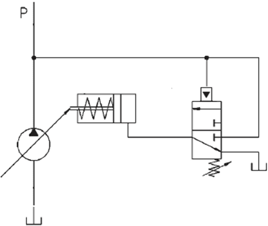
Look at how the pump works inside.
The bias spring (non adjustable) always tries to swivel the pump to max displacement.
When the set pressure is reached the adjustable pressure valve opens allowing oil into the swivel cylinder which swivels the pump back against the bias spring.
This swivel cylinder is the integrator.

The schematics in the datasheet for the PVB5 are a not that clear
On at page 14 in this datasheet there is a fairly good schematic:


Edit: an even simpler theoretical sketch here
2-Figure2-1_hwy238.png
 
The volume of the cylinder that actuates the swash plate adds up the fluid that the pressure control valve is feeding it. That conceptually sounds like integration to me.
 
The volume of the cylinder that actuates the swash plate adds up the fluid that the pressure control valve is feeding it. That conceptually sounds like integration to me.
This is why on 16 Jul I made the comment that this is a good question to think about.
I can understand why you think this but you need to understand the difference between integrating and non-integrating systems.

Look at the document hydtools posted. The graph of flow vs pressure shows the flow increases with the pressure drop. This is a simple proportional band. If there was an integrator then the flow would not drop except when the demand makes a sudden increase.

In a hydraulic cylinder the open loop model has no integrator for velocity but there is one for position. Same system so why the difference? It depends on what you are trying to control.
You need to understand the difference between integrating and non-integrating systems. A non-integrating system goes back to ambient or quiescent state when the control signal gone. In a hydraulic system system the velocity drops to zero but the position does not revert back to the original position because position is an integrating process.

Likewise the ambient position for the pump is the spring extended in the diagram Jacc posted. It will not hold the swash plate position when the pressure is gone to oppose the spring.
Trust me on this.
BTW, I got inducted into the IFPS hall of fame for my work in motion and force control and control theory for hydraulic systems and the flow vs pressure plots show that there pressure compensator is a simple proportional band.

Temperature control systems are non-integrating. If the control/power is taken away the cool down or warm up to ambient temperature. Accumulators are integrating systems. They integrate the net flow.


Peter Nachtwey
Delta Computer Systems
 
Status
Not open for further replies.

Part and Inventory Search

Sponsor