Eng-Tips is the largest engineering community on the Internet

Intelligent Work Forums for Engineering Professionals

Attractive Drawings 5

Status
Not open for further replies.

drawoh

Mechanical
Oct 1, 2002
8,860
0
0
CA
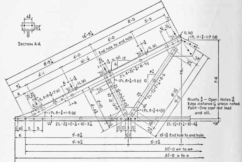
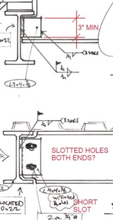
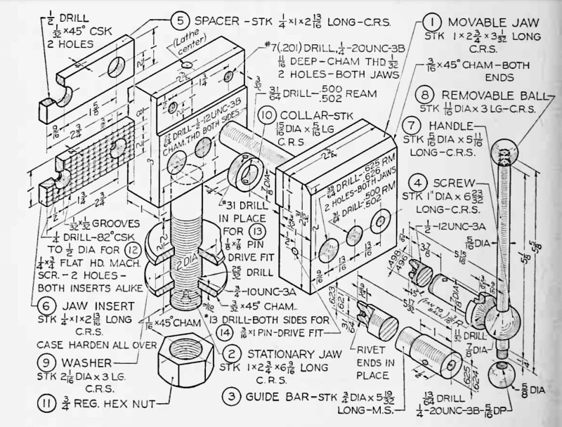
I am reviewing drawings here and I am being a bit of an asshole. We are a manufacturing service company and all of our drawings may be shown to the customer. In addition to being clear, we need them to look good and professional.

I am asking for well organized drawings with consistent fonts, with dimensions, notes, section lines and whatever positioned to be clearly visible. I don't want dimensions line crammed together such that I cannot see which dimension and which feature they apply to.

Is there a good article or other reference on this? Do I need to sit down and write one?

--
JHG
 
Replies continue below

Recommended for you

Drawing posted by Dik said:
2pc 3/4"Φ A325 Galv. Bolt Assemblies @ each xBrace connecreono

I would say:

1. Shall I assume that "A325" is ASTM A325? Withdrawn and replaced by ASTM F3125 in 2016 - which still uses "A352" as a grade designation. Type SC, N or X? Should the galvanizing be per ASTM F2329 or ASTM B695?
2. What is "connecreono".
3. Does this apply only where two cross-brace members connect, or also where a cross-brace connects to a vertical member?
 
dik said:
and another...
Looks good.
I wish I could see more mechanical component drawings, with tolerances, done like that. These became very rare. Usually when the appearance is meticulous, the content is good as well.
 
Thanks Mint... my notes that accompany my review include:

FASTENER (HIGH STRENGTH BOLTS)
-HS BOLT SPECIFICATION TO ASTM F3125, GRADE A325. THREADS CAN BE INCLUDED IN THE SHEAR PLANE. INSTALLATION SHALL BE ‘SNUG TIGHT’ U/N.
-BOLTS FOR BRACING TO BE INSTALLED SLIP CRITICAL. HARDENED WASHERS SHALL BE USED. ALL FAYING SURFACES SHALL BE CLEANED TO CLASS B. BLAST CLEANING IS REQUIRED FOR A SLIP COEFFICIENT = 0.50.

The drawing is only part of my review... I often don't have a 'full deck' when it comes to reviewing shop drawings and I may not know what is Specified or on the drawings, and I always include a list of 'Project Exceptions' to the Contract documents for the EOR to review. These exceptions are the criteria I have used for review, and if the material in the exceptions is followed, the work is safe and to code.

Galvanising is covered under the 'Coating Systems' part of my exceptions. My review exceptions generally have 2 or 3 pages of exceptions and my seal has a note:

Clipboard01_rjuyff.jpg


If bracing to a vertiical member, there would likely be a detail for that condition. I just like the linework from this client...


-----*****-----
So strange to see the singularity approaching while the entire planet is rapidly turning into a hellscape. -John Coates

-Dik
 
Sorry CWB1, but there are dimensioned details of the gusset to the HSS connections... As I noted in the earlier detail... if information is needed, or clarification, I add it. I'm generally OK with checking stuff myself... just like below:

Clipboard01_ykzcat.jpg


Their projects are small, and I still like their artwork...

-----*****-----
So strange to see the singularity approaching while the entire planet is rapidly turning into a hellscape. -John Coates

-Dik
 
I enjoy seeing legacy prints, drafting styles, hand-lettering, etc but dont consider it professional in our clean, crisp CAD era so won't approve it. There are certainly occasions when a quick hand-drawn sketch is appropriate for markups, white-boards, etc, but not for records or external sharing. The other big issue I have with the examples is cramming multiple prints' worth of data onto one. Prints should be structured to have separate component, assembly, and process levels for simplicity and clarity.
 
CWB1, I agree.
We have a Sr Engineer here that wants all his dwgs on B-size. Regardless the level of detail. They are unreadable, just cr*p! I refuse to make dwgs for him.

Chris, CSWP
SolidWorks
ctophers home
 
Well, ask him to read Section 4.5 - Letter Height and Tables 1 and I-1 in ASME Y14.2-2008 ("Line Conventions and Lettering").

Best regards,

Alex
 
The projects from this fabricator are all small... but it's a treat to see his handiwork.

-----*****-----
So strange to see the singularity approaching while the entire planet is rapidly turning into a hellscape. -John Coates

-Dik
 
I have showed him all standards, he wants it his way.
Over the past 10 years, I noticed there are less drafting positions. Companies are allowing engineers to make their own dwgs. No training.
This allows people to make dwgs however they please. Management doesn't care, as long as they are getting done on schedule.
I have experienced this at about 4 different companies now (mid size to start ups). Large corps follow standards.

Chris, CSWP
SolidWorks
ctophers home
 
Burunduk,

Wow!

That was not generated as part of a design process. It was done afterwards.

One of my issues is that one of our customers got drawings done by someone who "drew" in the largest scale they could. The drawing does not have proper projections, and there is no whitespace around the views. The drawings are almost unreadable.

If you tell the drafter who made your view to make his jaws 1/2" wider, they will have to clobber you over the head with a chair.

--
JHG
 
Status
Not open for further replies.
Back
Top