Continue to Site

Eng-Tips is the largest engineering community on the Internet

Intelligent Work Forums for Engineering Professionals

  • Congratulations SSS148 on being selected by the Eng-Tips community for having the most helpful posts in the forums last week. Way to Go!

Autodesk Inventor and Solidworks - comparison 3

Status
Not open for further replies.

EighthBen

Automotive
Dec 22, 2010
32
I am starting this discussion here, on eng-tips forum, and parallel discussion on Solidworks forum. I think users here, on eng-tips, might be more experienced in both programs than at solidworks forum, which is the main reason for duplication.

So, I have received a job invitation to the company which uses Inventor. Being only a SW user, I have decided to make myself an investigation of this program before the interview, as since now I have only formed my opinion about Inventor based on rumors on the internet.

Firstly, I found this in depth comparison of two products:
Inventor VS Solidworks


Though being a fairly deep comparison of the overall possibilities, this article lacks the feature-to-feature comparison. I had access to some training courses of Inventor, so I decided to learn myself the basics, and to get the opinion about this CAD package, by comparing it to SW: scaling the strength of the exact functions which I use everyday, and which are essentially important to me as an industrial engineer.


A few statements:

1. I am not commercially (or in any other way) interested to represent Solidworks, I just use it for my work

2. I tried to be as objective as possible, and to avoid statements as "I like this more". Though, some places are obviously better in one package or another. I have consulted a colleague of mine for this article, who is a 1 year user of Inventor as daily driver, and also has strong basics of Solidworks. He confirmed my thoughts on topics "opinion based"


The conclusion is this: I am astonished of the popular opinion for these two packages being the same level. I have no idea how people can come up with this opinion and say that "they are different, but with similar possibilities". Comparing the functions I use daily, Solidworks is much, much stronger system.


Below is my feature-to-feature comparison of these two CAD packages. I hope this could help deciding which system to get into for people who haven't tried these packages (or not both of them) themselves. I would also like to encourage users of both packages to input their opinion to this topic.

Well, the behavior of eng-tips forum interface is fairly limited. Therefore it would be very difficult for me to format all the listing and colors. So, instead of posting the direct comparison here as text, I attach the word document to this thread.

 
 http://files.engineering.com/getfile.aspx?folder=f346fdb7-2e3a-41e3-9d1f-928e94eae731&file=Inventorius.docx
Replies continue below

Recommended for you

Looks like a thorough comparison, thanks for posting. I'll only add when adopting any new tool you have to expect to change your workflow.

"Art without engineering is dreaming; Engineering without art is calculating."

Have you read faq731-376 to make the best use of these Forums?
 
I agree with MadMango. Your analysis appears to be thorough, but there is definitely the bias of knowing Solidworks better than you know Inventor. I have seen many comparisons, not implying this is true about yours, where the "competing" software got terrible reviews because the workflow didn't match identically to what the user wanted (or more to the point, was accustomed to from their main tool).

For example, there was a post here on eng-tips recently about comparing "Feature Recognizer" toolsets for imported geometry. The user marked Solid Edge poorly because that specific toolset was obsoleted and removed from the software several versions ago. With Synchronous Technology, feature recognition on imported geometry isn't needed anymore. None the less, the user had to score the software based on that tool and gave SE a bad grade. If the metric was different, for example how well does the software handle imported geometry, SE would have scored much higher.

My point is this, while Solidworks does appear to have many more options within each feature you compared which may streamline the design process, there doesn't appear to be anything preventing Inventor from creating the same geometry if you were to alter your workflow slightly. It may take a few more steps, but at the end of the day the same geometry is made.

Conversely, if I were coming from Inventor to Solidworks, I'd grade many of your positives for Solidworks as negatives because I wouldn't ever use those extra options and all they do is clutter the UI and make the process overly complex by having to sift through so many options, especially when picking up someone else's model to edit it.

Sorry if this sounded like a rant. I just want to make sure the big picture is considered by anyone who may review your comparison. Congratulations on taking the time to create the comparison, very thorough.

--Scott
www.wertel.pro
 
Here's the deal, from what I've seen people tend to fall in love with their first CAD system and no other will compare.

Try as you might to be subjective the familiarity with one system makes it hard to directly compare another unfamiliar system.

I learned Solid Edge & Pro E at about the same time - so as they existing circa 1999-2000 I can give a reasonably fair assessment though I never used any of the really advanced stuff at that time. For any other comparison I know I'm going to be biased.

Posting guidelines faq731-376 (probably not aimed specifically at you)
What is Engineering anyway: faq1088-1484
 
Kenat... I still hate AutoCAD r9.

"Art without engineering is dreaming; Engineering without art is calculating."

Have you read faq731-376 to make the best use of these Forums?
 
In the past I have used AutoCAD 14 and later revisions up to 2003, Inventor 3, Solidworks the original up to 2006, I just started using SW 2016 again, it was like learning a new program all over again compared to 2006. I also use Geomagic design 2016/17. Almost all of these programs have their strengths and weaknesses. Eight ben's comparison is quite an in depth one
I used to describe Solidworks and Geomagic as the difference between playing Badminton and tennis. They are both played on a court over a net with racquets, but there the similarity ends, something that works well for one game will totally mess you up for the other. People need to keep this in mind when they switch from one program to another.
B.E.


You are judged not by what you know, but by what you can do.
 
Badminton vs. Tennis... very apt comparison, BE.

I have learned and used both SW and Inventor. Not at the same time. Last SW contact was 2010. Generally I enjoy(ed) using both.

8thBen:
Since you're going to be working more in Inventor, here are some tips where you had difficulty (Yes, a lot of workflow comments).

1e) this supposed feature was added about 2 years ago, to fix to the reciprocal problem: drawing sketch lines too small/big and upon placing the first dimension the line distorts the entire sketch. Now the "float away" problem is managed by constraining at least one line to the sketch origin. Set it to be projected into the sketch every time (application options/sketch...)

2e)iv) slots are sketched first in Inventor.

2g)ii)2) sweep does not need the profile at the end of the path. I have done this many times. I also find Inventor can sweep when the path and profile don't intersect (usually doesn't cause a failure).

2h)i)1) Doesn't Inventor have a hole table function? I don't use it often - my hole patterns aren't usually very complicated, or they're just sketch driven.

2i) Lofts in SW used to require guide rails to be selected just-so. Is that still the case? Inventor can get testy when lofting parts with guide rails.

3)1)c) I prefer assembly mates that represent something tangible in physical objects (insert, flush, axial, etc.). The SW "width" mate sounds like it lines things up in a row...

3)2)b) "chain" pattern may be terminology used in SW so I don't recognize it. Inventor can "nest" patterns - is that what you mean?

3)8) The way you describe is inconvenient, true, but there's a better way, through using derived parts.

4)7) can you explain how section view is more powerful in SW? I'm curious.
4)14) I use a lot of large assemblies and this takes some careful management of "level of detail" in Inventor. Does SW do this? The "resolved/express" selection in Inventor is next to useless ( as you can tell) but it's not the whole story.


If I may suggest some other features worthy of comparison, my picks would be:
(parts) Derived parts
(assy) Derived assemblies
(assy) Degree of freedom analysis
(dwg) Use and editing of Styles (lines, balloons, dimensions, leaders, etc.)


STF
 
KENAT said:
Here's the deal, from what I've seen people tend to fall in love with their first CAD system and no other will compare.

Try as you might to be subjective the familiarity with one system makes it hard to directly compare another unfamiliar system.

I learned Solid Edge & Pro E at about the same time - so as they existing circa 1999-2000 I can give a reasonably fair assessment though I never used any of the really advanced stuff at that time. For any other comparison I know I'm going to be biased.

This is true - as you learn your first CAD system your brain adopts that system's way of organizing and solving design problems. Unless you learn your second CAD system much more deeply than the first one, I suspect KENAT's observation is generally true. You tend to miss the things that are absent more than you appreciate the new tools you gained.

I will say this - most all modern 3D CAD systems can do work well and efficiently when the work roughly agrees the software capabilities. Having more features and interface options is not always more efficient - because KISS. A simpler system helps a group of workers to work more consistently, will tend to have fewer bugs and unwanted interactions, will be more be compatible with PDM software, be forward compatible in later versions, is less expensive to buy/own, frees your mind to think more about the design and less about the software, and easier for any one worker to remain competent. The simpler system may slow down the super-users a bit on the whole, but it can speed up a group of users.
 
I am sorry for my late come back, I was busy


swertel said:
swertel (Mechanical):
23 Aug 16 14:19
I agree with MadMango. Your analysis appears to be thorough, but there is definitely the bias of knowing Solidworks better than you know Inventor. I have seen many comparisons, not implying this is true about yours, where the "competing" software got terrible reviews because the workflow didn't match identically to what the user wanted (or more to the point, was accustomed to from their main tool).

<>

My point is this, while Solidworks does appear to have many more options within each feature you compared which may streamline the design process, there doesn't appear to be anything preventing Inventor from creating the same geometry if you were to alter your workflow slightly. It may take a few more steps, but at the end of the day the same geometry is made.

Conversely, if I were coming from Inventor to Solidworks, I'd grade many of your positives for Solidworks as negatives because I wouldn't ever use those extra options and all they do is clutter the UI and make the process overly complex by having to sift through so many options, especially when picking up someone else's model to edit it.

Very interesting idea of yours - that less features can bring less confusion. I must agree that if the user is poorly trained, then the less options he has, the easier work is.
Of course, all options require some user input, therefore expanding menus and other user interface. I do not agree that less options means more power due to cleaner software interface and simpler feature tree. In my opinion, the user must be adequately trained to obtain the required task in the fastest and the most reasonable way. There are times when using more complex features brings more confusion than advantages, but Inventor looks to require additional geometry or other features for so many tasks that it requires more features do achieve the design, and I will dare to say - more time. Don't you think?


SparWeb said:
SparWeb (Aerospace)
2e)iv) slots are sketched first in Inventor.
Sorry, not sure what you mean. In SW: you put a "Point" in Hole wizard environment, and all the slot geometry is inserted automatically. Can you explain your expression?


SparWeb said:
2h)i)1) Doesn't Inventor have a hole table function? I don't use it often - my hole patterns aren't usually very complicated, or they're just sketch driven.
It is a different thing. Say you want to pattern a feature for 10 instances, lets say every 10 mm. But you want to skip instances Nr. 6 and Nr. 8. You will get instances at these dimensions:
10 mm
20 mm
30 mm
40 mm
50 mm
70 mm
90 mm
100 mm


SparWeb said:
2h)i)1) Doesn't Inventor have a hole table function? I don't use it often - my hole patterns aren't usually very complicated, or they're just sketch driven.

Table driven pattern is a different thing, requiring more time to implement, and used in more difficult cases (at least in SW)


SparWeb said:
2i) Lofts in SW used to require guide rails to be selected just-so. Is that still the case? Inventor can get testy when lofting parts with guide rails.
As I said, I never use Lofts in my solid modelling, so I haven't compared the features. I searched some youtube videos, this one represents SW intro to loft quite well:

Though, I sometimes do use sheet metal loft, this is shortly what it is:
The bends can be designed as "formed" (like in the video) or as "bended" when you have many small bends.


SparWeb said:
3)1)c) I prefer assembly mates that represent something tangible in physical objects (insert, flush, axial, etc.). The SW "width" mate sounds like it lines things up in a row...

This is a good representation of it:
I use it very, very often. I would definitely miss it in Inventor.


SparWeb said:
3)2)b) "chain" pattern may be terminology used in SW so I don't recognize it. Inventor can "nest" patterns - is that what you mean?
This is what I mean:
The "beautiful" representation of flexible chain works only in demo videos. Anyhow, I design chains with this pattern when designing chain conveyors with attachments, when e.g. every 500 mm a chain link has an attachment welded to it, and it is important to see it how it behaves when the transported item is moved from one conveyor to another. I use it a lot (I design sawmill machinery, where wooden planks are transported), we reduced amount of mistakes after starting to use it. Chain transporter:


SparWeb said:
3)8) The way you describe is inconvenient, true, but there's a better way, through using derived parts.
Hard to explain in words. If you want to discuss it please tell me, I will record a video


SparWeb said:
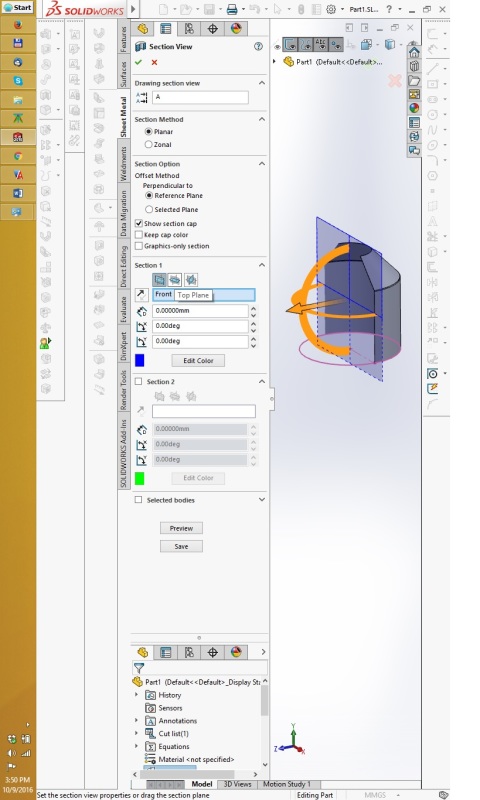
4)7) can you explain how section view is more powerful in SW? I'm curious.
This is how SW 2016 section view options looks like:
section_view_ocxuu4.jpg

In SW 2017 it became even more powerful, capable to display sectioned part in transparent, not totally hidden. But 2017 version is not official yet.


SparWeb said:
4)14) I use a lot of large assemblies and this takes some careful management of "level of detail" in Inventor. Does SW do this? The "resolved/express" selection in Inventor is next to useless ( as you can tell) but it's not the whole story.

Pleas watch this video:
Shortly:
1) Resolved: all part documents are fully opened
2) Lightweight: all part documents are opened, but only the 3d parasolid section is being read, not the full information of features
3) Large assembly mode: Same as 2, but also some additional system options are set to certain values for faster opening and better performance. Sometimes, part files are not event opened, but I am not sure how this works.
4) Large design review only the assembly file itself is opened, and it represent the parasolid model. Opens instantly.

I would say these modes works pretty well.

NOTE! I wrote that:
14.b. In drawing files, Inventor has the possibility to optimize drawing view generation with “raster” functionality, drawing rebuild can also be paused from updating the drawing view from the model. No such functions in SW

I can't believe I forgot that it IS possible in SW. I used to use it with large production lines. I saved me, otherwise technical drawings of full assembled machines would had been near to impossible to handle. In "SW" this option is called "Automatic view update". There is a quite good discussion about it here:


SparWeb said:
If I may suggest some other features worthy of comparison, my picks would be:
(parts) Derived parts
(assy) Derived assemblies
(assy) Degree of freedom analysis
(dwg) Use and editing of Styles (lines, balloons, dimensions, leaders, etc.)

Firstly, let's finish our current discussion topics, then we can do it. You write your ideas what is important to you and how you use it in Inventor, and I will respond how I do it in SW.

PS: I refused the job offer with Inventor. CAD package was not the only reason that made my decision, but now I know that I would not consider working with Inventor daily. I emphasize that it is my opinion only :)
 
Hi again,

Glad you came back to continue this subject.

Some opening coments before following up with your questions:

I dislike the Windows ribbon. I also despise it. Sometimes I get even angrier.
Autodesk has chosen to incorporate the ribbon into both AutoCAD and Inventor. In AutoCAD, I am such an experienced user that I can hide it and make use of that screen space instead. In Inventor, the workflow doesn't work without the ribbon and have no choice. This my greatest obstacle to using Inventor, but it's not Autodesk's invention, so I can forgive them.
My suggestion to making Inventor more useful is to move every single button from the concealed fly-outs of the ribbon into the visible panels. On a single screen larger than 1920 pixels wide there is no menu in Inventor that doesn't have enough space for all of the buttons to be visible so there is no need to conceal any of them. In fact, even with every single button moved from fly-out to main panel, the ribbon still wastes 50% of the space it takes up in most menu selections.


I make "very" complex drawings from Inventor models. I don't say this to sound self-important or full of myself. What I mean is that I have never ever seen a drawing as complex as the ones I create every day shown in a demo video, tutorial, youtube, or so-called expert training session. Never. I always get a kick out of the mickey-mouse drawings that are hastily assembled in youtube videos. Many of my co-workers make drawings as complex as the ones I make, and this subject is what we discuss about Inventor the most. Not model making. How much time do your typical drawings take you to complete? Hours, days, or weeks? I ask because this factor has a profound influence on my own workflow.


2e)iv) slots are sketched first in Inventor.
Sorry, not sure what you mean. In SW: you put a "Point" in Hole wizard environment, and all the slot geometry is inserted automatically. Can you explain your expression?

On any part, create a sketch. On that sketch, create and constrain a point where you want the slot.
Autodeak cleverly conceals the Inventor slot tool in a fly-out on the sketch panel - see my ribbon rant above.
Once you've set up the slot in the sketch, close the sketch, and use the sketch to generate the slot in the part.


2h)i)1) Doesn't Inventor have a hole table function? I don't use it often - my hole patterns aren't usually very complicated, or they're just sketch driven.


It is a different thing. Say you want to pattern a feature for 10 instances, lets say every 10 mm. But you want to skip instances Nr. 6 and Nr. 8. You will get instances at these dimensions:
10 mm
20 mm
30 mm
40 mm
50 mm
70 mm
90 mm
100 mm
Table driven pattern is a different thing, requiring more time to implement, and used in more difficult cases (at least in SW)

Oh, same thing is available in Inventor. Generate the pattern first. This can be a pattern of holes, features, or parts in an assembly. Select and expand the list of patterned items in the feature tree. Suppress the ones you don't want. This is convenient, but it goes haywire if you change the number of items in the pattern later.


2i) Lofts in SW used to require guide rails to be selected just-so. Is that still the case? Inventor can get testy when lofting parts with guide rails.

As I said, I never use Lofts in my solid modelling, so I haven't compared the features. I searched some youtube videos, this one represents SW intro to loft quite well:
Though, I sometimes do use sheet metal loft, this is shortly what it is:
The bends can be designed as "formed" (like in the video) or as "bended" when you have many small bends.


Thanks for the links. Lofting a part in Inventor has many more possibilities than were shown in those links, though I expect they are also there in SW, since I remember using them a decade ago. If lofts aren't a kind of feature you use in depth, then I won't worry about trying to make comparisons.


3)1)c) I prefer assembly mates that represent something tangible in physical objects (insert, flush, axial, etc.). The SW "width" mate sounds like it lines things up in a row...


This is a good representation of it:
I use it very, very often. I would definitely miss it in Inventor.

I see. It's an abstraction, from the surrounding geometry. Inventor doesn't encourage this style of assembling parts, and references all mates to a specific feature, surface or edge. I can see how it would be handy. The example in your video, however, would conceal to a designer the clearance and "slop" in the fit of the dove-tail parts if it was constrained that way. An Inventor user would constrain the two sloped sides of the slider to the sloped sides of the slot, and then it would function as shown. There would then be a gap at the bottom of the slot and the Inventor designer would be keenly aware that these two surfaces cannot be mated together - a condition that also exists in the real world and serves the designer well to be aware.


3)2)b) "chain" pattern may be terminology used in SW so I don't recognize it. Inventor can "nest" patterns - is that what you mean?

This is what I mean:
The "beautiful" representation of flexible chain works only in demo videos. Anyhow, I design chains with this pattern when designing chain conveyors with attachments, when e.g. every 500 mm a chain link has an attachment welded to it, and it is important to see it how it behaves when the transported item is moved from one conveyor to another. I use it a lot (I design sawmill machinery, where wooden planks are transported), we reduced amount of mistakes after starting to use it. Chain transporter:


Nice feature. Inventor has a suite of mechanical tools, but I'm not familiar with them. I design structures, mostly, and the fasteners I use had to be modeled individually as iParts. The standard content intended for your average mechanical designer doesn't go far in my workplace. I've used some of the tools intended for plastic injection-molding to good effect when designing 3D-printed parts, a few times.


3)8) The way you describe is inconvenient, true, but there's a better way, through using derived parts.

Hard to explain in words. If you want to discuss it please tell me, I will record a video

Still curious.
I don't mind a verbal explanation, even if you think it's clumsy, to save you the trouble of making a video for an audience of 1.


4)7) can you explain how section view is more powerful in SW? I'm curious.
This is how SW 2016 section view options looks like:
In SW 2017 it became even more powerful, capable to display sectioned part in transparent, not totally hidden. But 2017 version is not official yet.

This is very interesting. Inventor's section views, when used in the part / assembly environments, is limited to just lopping off the ends / corners of things. And there is a completely separate means of making section views in drawings which makes little use of the model sections, if any.

Gladly cede the point to SW there!


4)14) I use a lot of large assemblies and this takes some careful management of "level of detail" in Inventor. Does SW do this? The "resolved/express" selection in Inventor is next to useless ( as you can tell) but it's not the whole story.

Please watch this video:
Shortly:
1) Resolved: all part documents are fully opened
2) Lightweight: all part documents are opened, but only the 3d parasolid section is being read, not the full information of features
3) Large assembly mode: Same as 2, but also some additional system options are set to certain values for faster opening and better performance. Sometimes, part files are not event opened, but I am not sure how this works.
4) Large design review only the assembly file itself is opened, and it represent the parasolid model. Opens instantly.

I would say these modes works pretty well.

Gotcha: Much more useful than the "canned" detail modes available in Inventor. Usually you must create a custom level of detail in order to control the complexity of a very large assembly.

Another point for SW.


NOTE! I wrote that:
14.b. In drawing files, Inventor has the possibility to optimize drawing view generation with “raster” functionality, drawing rebuild can also be paused from updating the drawing view from the model. No such functions in SW

I can't believe I forgot that it IS possible in SW. I used to use it with large production lines. I saved me, otherwise technical drawings of full assembled machines would had been near to impossible to handle. In "SW" this option is called "Automatic view update". There is a quite good discussion about it here:

AI & SW: tied


If I may suggest some other features worthy of comparison, my picks would be:
(parts) Derived parts
(assy) Derived assemblies
(assy) Degree of freedom analysis
(dwg) Use and editing of Styles (lines, balloons, dimensions, leaders, etc.)

Firstly, let's finish our current discussion topics, then we can do it. You write your ideas what is important to you and how you use it in Inventor, and I will respond how I do it in SW.

PS: I refused the job offer with Inventor. CAD package was not the only reason that made my decision, but now I know that I would not consider working with Inventor daily. I emphasize that it is my opinion only :)

OK, saved for later.

Hope your work situation is sorted out well. Still not easy times for folks to find work where I am, but I still have a good job. I hope good prospects come your way!

STF
 
Status
Not open for further replies.

Part and Inventory Search

Sponsor