Eng-Tips is the largest engineering community on the Internet

Intelligent Work Forums for Engineering Professionals

  • Congratulations waross on being selected by the Tek-Tips community for having the most helpful posts in the forums last week. Way to Go!

Autotransformer Zero sequence current

Status
Not open for further replies.

anggap

Electrical
Jun 28, 2018
27
0
0
ID
Hi all,

Recently there was single line to ground fault in my plant, below is the current based on the actual record on related relays:
one_line_usba0p.jpg


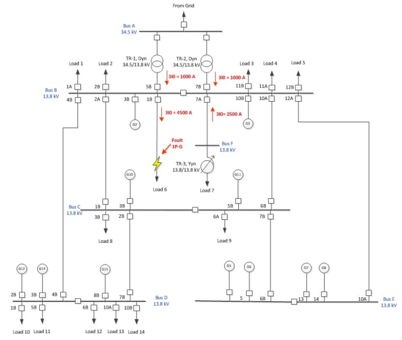
* TR1 and TR2 LV winding are connected to ground with low resistance NGR (1000A
* Neutral point of generators are connected to ground with high resistance NGR (10A)
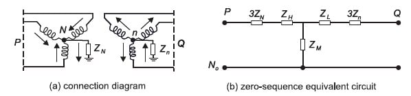
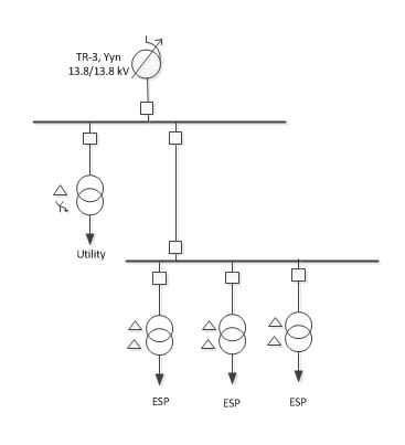
* TR3 is single winding autotransformer with no tertiary winding, the neutral point is solid grounded

Based on coordination relay study on easy power, it supposed to be no current flow at feeder 7A Bus B during fault at feeder 1B's downstream. But actually there is zero sequence current flow at that feeder which caused breaker 7B tripped by 50N relay.
note: in simulation I modeled TR-3 with two winding Yyn Transformer

Is it wrong to modeled the transformer (TR3) with two winding Yyn Transformer? because there is no single winding autotransformer in easy power.
I modeled it with two winding Yyn Transformer because the zero sequence circuit are the same.

zero_seq_xsy3py.jpg


Please advise

Thanks
 
Replies continue below

Recommended for you

I'm guessing that TR3 may have been modeled with a three legged core.
Try another model with a wye/delta transformer in place of TR3.
I think that you will see a heavy contribution to the fault.
A transformer with a three legged core has a phantom delta effect that may have caused your current.
Will Easy Power let you choose between a three lagged core\and a five legged core?
If so try modeling TR3 as both a three legged core and as a five legged core and see if there is a difference.
Is there any rotating load on TR3?

Bill
--------------------
"Why not the best?"
Jimmy Carter
 
I got your point, three leg core transformer will create additional ground path due to Zm.
3leg._jpg_wugy35.jpg

So, there will be current contribution from this feeder to the fault.

If I want to omit current contribution from this feeder, what should I do? Remove neutral to ground connection of this transformer?

Answer: Yes, if i try with Yd Transformer, there will be contribution to the fault.
In easy power, there is an option to choose whether shell type or core type transformer, but there is no difference for the fault current.
 
@KS227 Yes, but it should be not that significant because they are ESP motors.

@wroggent I model the transformer as Ynyn
 
OP said:
Yes, but it should be not that significant because they are ESP motors.
Did you mean to say;
" Yes, but it should be not that significant because they are VFD driven motors."?

Bill
--------------------
"Why not the best?"
Jimmy Carter
 
waross said:
Did you mean to say;
" Yes, but it should be not that significant because they are VFD driven motors."?

Only some of of them are VFD driven, but the main the reason is that they have small inertia with large impedance (cables) between the motor and connected bus.
 
What about the possibility of a delta tertiary in TR3? Could be buried with no external bushings, but its presence alone would be important even if not connected to anything.
 
@bholas Bus F is quite far from Bus B (30000 ft), so it is needed to boost the voltage.

@davidbeach TR3 connection is like this, I thinks there is no tertiary winding in TR3
AVR_htolaq.jpg
 
Motor contribution:
This may be more than you think.
With a single phase to ground fault the inertia is relatively unimportant.
The healthy phase(s) will continue to drive a DOL motor and the motor will transfer power from the healthy phases back into the faulted phase.
The slip frequency of the faulted phase will be 100% and the backfed current may be greater than the normal running current.
I believe that the current will be in the order of 1/3 times locked rotor current. Can anyone verify this? Thanks.
You are probably correct and the feeder impedance renders the motor contribution negligible.
The point is that motor contribution into a single phase fault may not follow the same rules as motor contribution into a three phase fault, particularly in regards to inertia.

Bill
--------------------
"Why not the best?"
Jimmy Carter
 
I think that David's on the right track.
I suspect;
1. A wye delta connection. ie: buried tertiary.
2. A three legged core and the phantom delta effect.
3. A five legged core with less than 100% cross section of the return cores causing saturation and a partial phantom delta effect.
4. Possible but not likely, a motor contribution.

Bill
--------------------
"Why not the best?"
Jimmy Carter
 
Thanks David & Bill, I had always thought that this transformer have no tertiary winding. All study always model this transformer as Yyn transformer with no tertiary winding.
I've checked the old drawing and I found that actually the T1-T6 terminals are delta connected. But I'll check to the plant to make sure how the actual connection is.

 
Status
Not open for further replies.
Back
Top