Eng-Tips is the largest engineering community on the Internet

Intelligent Work Forums for Engineering Professionals

  • Congratulations waross on being selected by the Tek-Tips community for having the most helpful posts in the forums last week. Way to Go!

Available bolted three phase short circuit current

Status
Not open for further replies.

kply_231

Electrical
Apr 4, 2016
18
0
0
CA
Hello

I am conducting an arc flash study of a power distribution system using IEEE 1584. For calculating the arcing current, I need to determine what's the available bolted three phase short circuit current. How is this determined? Is it the utility that provides this parameter? Does this value change at each bus level (from upstream to downstream)?
 
Replies continue below

Recommended for you

The utility will provide you will the equivalent Thevenin impedance at the point of common coupling (or will provide 3-P fault current and X/R ratio). You will then need to calculate the bolted three phase fault currents at all of the busses applicable in your study. You'll need to use something like SKM, ETAP, easypower, etc.
Yes, these will change at each bus level due to increasing impedance of cables / transformers, as well as induction motor contribution.
 
Hi GPTech

Thanks for your quick reply.

I am currently in the process of developing a spreadsheet using the formulas in CSA Z462 ( which is in turn referring to IEEE 1584) for calculating the bolted three phase short circuit current. I am not using ETAP or SKM because this is just a one single project that I am doing.

I understand how the transformers between the buses will change the bolted three phase fault current. And, although I agree that cable impedance will have an effect, I can't find any reference in CSA code Z462 where they are considering the cable impedance.

Can you please explain in little more detail how an induction motor affects the bolted three phase short circuit current?

Thank you.


The "Available Short Circuit Current" is a defined term for the steady state fault current, after the decay of the original asymmetrical, offset component of the fault current.
At the instant of a three phase fault, the induction motors become induction generators and feed into the fault.
In one instance, a 400 HP wound rotor motor direct coupled to a fan was subjected to a three phase flash over at the main contactor.
The motor became an induction generator adding current to the fault.
How much current.
Not known.
But enough current that the resulting violent de-celleration resulted in the coupling being "blown up" and both the motor shaft and the fan shaft being bent.
An induction motor's contribution to a fault is sometimes estimated as motor starting current for the first several cycles of a fault.

Bill
--------------------
"Why not the best?"
Jimmy Carter
 
If you are doing this by hand, a good reference to follow would be the "MVA method" (google it). It is not an exact method, but it gives you a good indication of the fault magnitude at your desired bus. Like Bill said, induction motors will become induction generators and feed into the fault. However, this fault current decays exponentially. It is standard to use a constant induction machine current value (~6x FLA) for 5 cycles for arc flash energy calculations.

This means that you will have a step function for this calculation:
a. 0ms-83ms: symmetrical 3 phase fault current (utility contribution) + all induction machine fault current (motor contribution)
b. 83ms-trip time: symmetrical 3 phase fault current (utility contribution)

You will then have two arcing current values to be used in a piece-wise incident energy calculation.
 
Hi GPTech & Bill

I am having a hard time to get the available bolted three phase short-circuit current (symmetrical rms), kA from our utility.
I am trying to calculate the arcing current using the below formula given in IEEE 1584 -

Log(I[sub]a[/sub]) = K+0.662log(I[sub]bf[/sub])+0.0966V+0.000526G+0.5588V*log(I[sub]bf[/sub])-0.00304G*log(I[sub]bf[/sub])

This will help me to calculate the total incident energy.

Can we not calculate the bolted fault current using the Lee's method if utility is not providing the total available fault current?
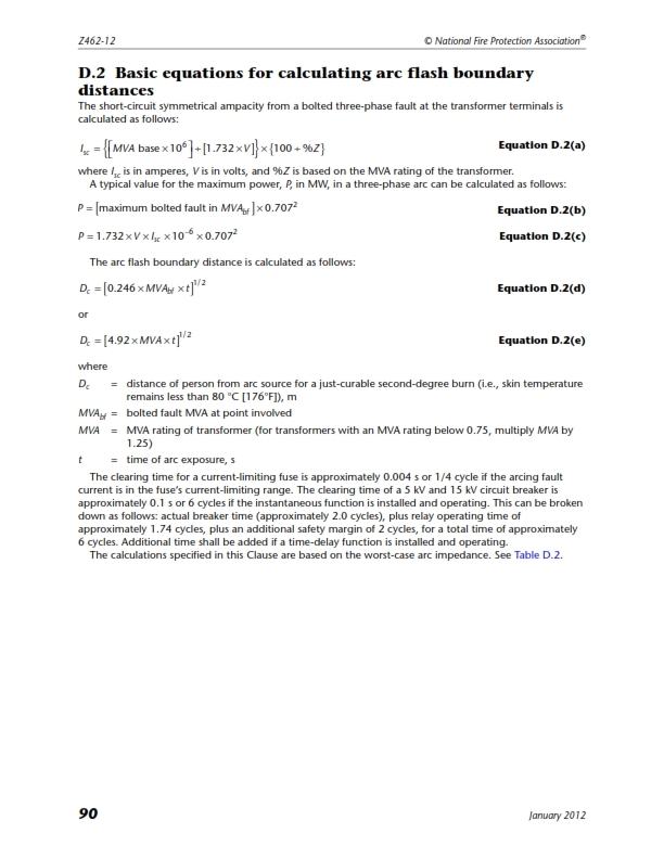
Lee's method requires only the MVA base, %Z and Voltage of the main incoming transformer for the below formula -

I[sub]sc[/sub] = {(MVA[sub]base[/sub]*10^6)/(1.732*V)}*{100/%Z}

Am I going in the wrong track here?

 
Look at your supply transformer. %imp voltage or %Z. This is the voltage required to force full load current through a bolted short circuit at the transformer terminals. (At operating temperature. It may be slightly lower with higher current when the transformer is cold.)
Rated current divided by the %Z will give the Available Short Circuit Current when the transformer is fed from an infinite source.
For relatively small transformers on "Stiff" distribution circuits this is often an acceptable figure. It is the maximum current. This maximum value may be reduced by the Available Short Circuit Current of the source.
sajujsam: I am not sure of your convention but the last (*) in your equation may need to be changed to a (/)


Bill
--------------------
"Why not the best?"
Jimmy Carter
 
The maximum fault current, neglecting source impedance, may not be the worst case for arc hazard because lower currents may have significantly longer fault clearing times. Using the main transformer impedance does not take into account the impedance of distribution conductors to the point of the fault. It also does not consider motor fault contribution.
 
sajujsam:

Lee's energy equation was derived for medium voltages over 15kV as it assumes little arcing impedance. It is a very conservative estimate for incident energy, but has nothing to do with calculating the bolted fault current.

Before you get into the arcing current and subsequent incident energy equations I would first focus on acquiring an accurate bolted fault current. Depending on the voltage, the arcing current may have high error (for example, at low voltages a 95% probability will give you +/- ~25% error, while at medium voltages a 95% probability will give you +/- ~15% error). As noted above, this can have a HUGE impact on the eventual energy calculated if your protective device is highly inverse (like with fuses or VI/EI 51 curves).


Hi Bill (Waross)

Please see the extracted page from CSA code Z462-12. The second equation that I quoted is equation D.2(a)
What I meant by '*' is 'multiply'. I am not sure if I understood you when you say to replace '*' with '/'.
CSA_Z462--12_106_mhkevc.jpg
 
Hi GPTech

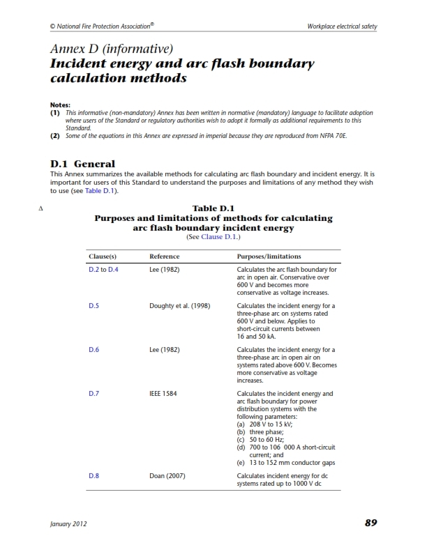
Below is an extracted page from CSA code Z462-12 where they recommend Lee's method for determining arc flash boundary & incident energy. They say that Lee's equation becomes conservative over 600V.

_105_x847mg.jpg
 
Hi sajujsam,

The Lee (1982) equations shown in Table D.1 are for incident energy and not the bolted fault current. Keep in mind that the Lee method is theoretically derived and is very conservative. If you read the appendices of the IEEE 1584 standard, you can see how Lee's incident energy model was derived and under what conditions and assumptions. Generally, the Lee equations would only be used in practice if your system does not fall within the range of the empirically derived equations (shown in section 5.1).


sajujsam said:
Below is an extracted page from CSA code Z462-12 where they recommend Lee's method for determining arc flash boundary & incident energy. They say that Lee's equation becomes conservative over 600V.

Note that nothing is "recommended" but the Annex summarizes the available methods. Also note that Lee's equation is applicable for an open air fault. If you are in an industrial facility, this would not be applicable as your faults would be enclosed arc faults.

There is an IEEE paper (PCIC-2009-16) which examined the effect of utility available fault current on the incident energy calculations and provides a list of reasonable assumptions that can be made in the event that actual utility fault information is not available.
 
Status
Not open for further replies.
Back
Top