Continue to Site

Eng-Tips is the largest engineering community on the Internet

Intelligent Work Forums for Engineering Professionals

  • Congratulations waross on being selected by the Eng-Tips community for having the most helpful posts in the forums last week. Way to Go!

B31.3 application for 76" cooling water pipeline

Status
Not open for further replies.

vtpsantos

Mechanical
Apr 12, 2023
7
Hello guys,

We are design a 76" pipeline for a cooling water system. It will be made of A36 plates which we need to determine the thickness. So, based on equation 3a given by B31.3 and process data, we reach a thickness of 5/8". But I'm in doubt about two things:

1) Is there a limit about pipe size range to apply this code or for this situation of application? I quickly looked another B31 sections but B31.3 seems the most suitable. If you guys have another codes (not only ASME) or methods of evaluation that could be applied or give me a double-check, I'll do this for sure.

2) Although this thickness satisfies the pressure condition, the relation D/t still higher than 100. I'm really concerned about localized stress due to pipe and content weight. If we can't increase plate thickness and based on B31.3, should we evaluate this primary stress on pipe wall at support points using FEM?
 
Replies continue below

Recommended for you

You could try either B 31.1 or look at some of the AWWA codes for water, especially when you get that big as they are probably more suitable.

I don't think there is a size limit, but your issue for pipe on supports is going to be shear and bending and point loading.

Your point loading may need FEM if you're going skinny steel pipe and not something like GRE or concrete.

Remember - More details = better answers
Also: If you get a response it's polite to respond to it.
 
I searched in AWWA C2xx series and didn't find any procedure to calculate thickness, but I'll try AWWA M11. B31.1 will give us a more conservative result, I'll try it too.

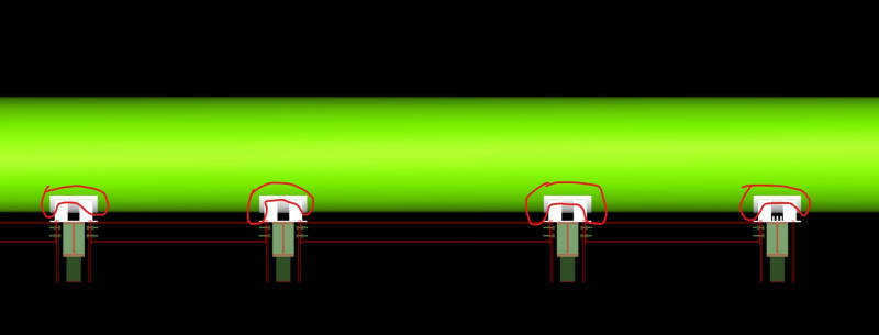
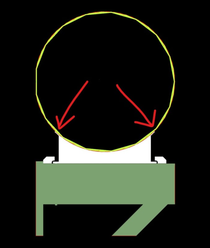
Talking about need of FEA, my concern is related not only on the possibility of pipe flattening, but stress rise and concentration on support points, in the plate around pipe saddles (red areas/indications below). Of course it is directly related with pipe support span, but we can simulate some scenarios and find the 'ideal solution' between rising thickness or reducing pipe support span, or evaluate the need for some kind of pipe reinforcement.

engtips_liqkhw.jpg

engtips2_kpiqdw.jpg
 
Did you mean to draw it a series of flat sections?

That is a very thin pipe and this supports don't look big enough

I would look at PE, GRE or cast iron in comparison.

Remember - More details = better answers
Also: If you get a response it's polite to respond to it.
 
I understood your appointment about material changing, but it isn't a comfortable solution for our client. Sometimes this kind of pipe is made of A36 welded on site.

About pipe flattening, what I meant to say is the possibility of occurring pipe buckling/ovalization due to excessive loads on these saddles supports. This configuration (outside diameter = 76" and thickness = 5/8") is out of condition D/T<=100. Using FEA we could determine if this thickness is enough, this would be my personal choice. But I'm searching for alternative codes to try to escape from FEA.
 
What you are designing is close to hydro station Penstocks.

Steel Penstocks - Task Committee on Steel Penstock Design of Pipeline Planning and Design Committee of the Pipeline Division of ASCE


This refers to ASME vessel codes for local stress calculations.

In our industry we design steam and hot water lines up to DN1500 (60") and use FEA to ASME VIII-2 part 5 rules for the supports and local stress design.
 
Status
Not open for further replies.

Part and Inventory Search

Sponsor