Continue to Site

Eng-Tips is the largest engineering community on the Internet

Intelligent Work Forums for Engineering Professionals

  • Congratulations cowski on being selected by the Eng-Tips community for having the most helpful posts in the forums last week. Way to Go!

Back Pressure Valve on deep well application

Status
Not open for further replies.

scheideler

Civil/Environmental
Mar 18, 2016
6
Hello. I've browsed this forum for years but couldn't find any info on my current issue so I thought I'd post.

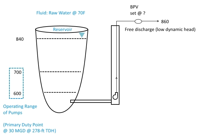
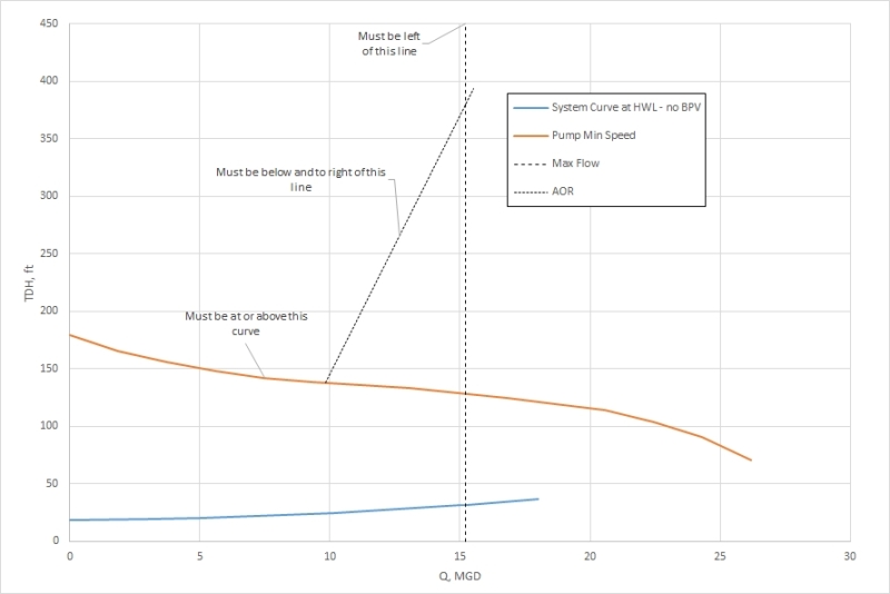
I'm part of a team designing a deep well pump set which is assigned to a certain bandwidth of water surface elevations, although the water will rarely be that low (emergency pumps). In order to keep the pumps ready, we will exercise them regularly. The pumps will be equipped with VFDs, but at the minimum turn-down speed they are nowhere near where the system curve is likely to be. I've got some curves attached.

I understand that a back pressure valve (or pressure sustaining valve) can allow operation of the pumps even when the water surface is quite high, but, because of limitations on the design, the pump intake and the valve have a difference in elevation of ~250-ft. The flow path with the valve is a bypass with smaller piping than the process flow, requiring reduced flow rate.

Here are my questions.

Does one of these valves essentially establish a flat system curve (ie, a setting of 300 ft (converted to psi) means 300 feet at all flows)?
Does the sustained pressure exist equally throughout the riser pipe, or is there a significant elevation gradient? In other words, if i know what head the pump needs to see, how do I translate this to the valve setting, far above the pump? I'd found that, in order to stay in a good operating range as shown in the attached curve, the pump needs to see about 200-ft of head. But if i subtract the elevation difference, that leaves a setting of -50 ft, which obviously seems ridiculous.
I'd considered just running through a partially-closed ball valve (we'll be burning head anyway, but not for sustained periods), but found that the cavitation would be severe; is this reasonable?

Thanks in advance for any tips.
Curves_hkvd2s.jpg
 
Replies continue below

Recommended for you

"Deep well" is in the eye of the beholder. In Oil & Gas your depths would be very very shallow, but I know what you mean.

The only positive thing that backpressure does for downhole pumps is to compress any gas that is in the pumped stream to make it take up less physical space (for the same mass flow rate). If your water source is a coal bed, then this can be an important consideration. If it is a conventional aquifer, then this is unlikely to be a major consideration.

The pump sees the sum of atmospheric pressure + backpressure imposed by the system + hydrostatic head of water at the pump discharge (0.433 psi/ft). If your pump is set at 250 ft BGL at sea level, with a system pressure of 45 psig, then the pump sees:
P(disch) = 14.7 psia + 45 psig + 250 ft * 0.433 psi/ft = 167.95 psi = 387.9 ft.

The pump head is P(disch) - P(suct). If you have 187.9 ft of water column on the suction side then 45 psig backpressure would give you the 200 ft of head you are looking for.

A decent backpressure valve like the Baird or Masoneilan will maintain the same backpressure regardless of flow rate. An air-actuated backpressure valve can work, but the controls get a touch messy.

David Simpson, PE
MuleShoe Engineering

In questions of science, the authority of a thousand is not worth the humble reasoning of a single individual. Galileo Galilei, Italian Physicist
 
I can't quite work out the different elevations and system here ( a sketch would help), but what control valve on the pump outlet does is introduce a vertical line on the system graph down from your pump head to the system curve line.

In your case then if the valve is at an elevation 250ft above the outlet of the pump then of course this needs to be taken into consideration. Equally, unless the head of the pump exceeds the elvation head, then you will not have any flow.

That's why profile is required to try and make sense of what you're trying to do.

Throttling using valves not designed for it (ball/gate) is bad for the valve - You can destroy a valve quite easily or at least damage the seats so much that they just won't work properly any more.

Remember - More details = better answers
Also: If you get a response it's polite to respond to it.
 
Thanks for the responses.

Of course I could've included more details. Process fluid is raw water at ambient temp. We have an emergency reservoir with 2 pumps sets, one for the top and one for the bottom elevations.

Zdas04, the main problem is we need to run the pumps, even briefly, when the suction pressure is ~100 psi. The operating pressure, at grade where the valve is located, is quite low, because we're just freely discharging at the top of the riser pipe. I'll look into the valve brands you mentioned.

LittleInch, I've attached a sketch. I'm not clear on your vertical line comment. My understanding was that the BPV would induce head on the system, effectively lifting the system curve. In effect, I need it to simulate a higher static head. Thanks for confirming about the throttling. Are there other valve types I should consider for this application? 30" diameter, 20 MGD, effective Cv of about 150?

Thanks to both of you.


Profile_sketch_xk8wpd.jpg
 
What are the units on the left in the graph? Numbers increasing upwards is really confusing me. Normally you would set your zero at either the surface (most common) or at the pump. Having a value of "600" at the pump is confusing me.

Let's ignore my confusion for a minute and assume the pump has 240 ft of suction head (about 108 psig) and your water table is 20 ft BGL. If you need 250 ft of head at the pump, then you would have to put 250 ft - 20 ft = 230 ft ≈ 100 psig backpressure.

David Simpson, PE
MuleShoe Engineering

In questions of science, the authority of a thousand is not worth the humble reasoning of a single individual. Galileo Galilei, Italian Physicist
 
The numbers on the left at feet above sea level.

Thanks.
 
Come on Dave, the units are pretty clearly elevation.... I suppose it is Friday afternoon ;-)

for your purposes, you are best working from the pump centreline elevation as zero.

You neglected to mention that your pump inlet had a static head of (actually I don't know what as you haven't listed the elevation of the pump...), but clearly between 250ft (max) and about 20? (min). Your pump has a differential head of 100 to 150 ft assuming your curve in the OP is actually total differential head?

Hence this now explains why you can pump with your valve at an elevation so far above the pump outlet.

Given that your inlet head / pressure seems to be quite variable, you probably really need to set your control valve to control on flow, not pressure unless for the operation you are doing the inlet head is quite stable.

I think it is better to draw a line vertically down from the head at the valve ( inlet head plus pump differential minus elevation difference from pump to valve) to the system curve. This is the head loss across the control valve.

To get a set flow with a fixed back pressure, then the values need to be constant.

you need some sort of control valve ideally - globe or perhaps a butterfly valve, but that's quite a big diameter with a decent flow so you really need to talk to a few vendors.

Remember - More details = better answers
Also: If you get a response it's polite to respond to it.
 
The application does not look like flow control to me. He's just trying to keep the pump from free wheeling during the exercise periods. In actual use (if ever necessary God forbid), they want all the water they can get.

David Simpson, PE
MuleShoe Engineering

In questions of science, the authority of a thousand is not worth the humble reasoning of a single individual. Galileo Galilei, Italian Physicist
 
Hard to understand what he his asking.

From the application, it appears that the problem will be when high water elevation will cause excess flow from the pump.
 
Thanks for all the responses.

It's not an issue of excess flow. In the curve at top, there's the pump curve, turned down to the lowest recommended speed. Then there's the system curve, which is incredibly low when the reservoir is full. The pumps were never meant to operate at this water level, and that water level is expected to be the default level. Only when this offline storage volume is being pumped out (ie, emergency conditions for the owner) will those pumps be put to their designed purpose. Unfortunately, we need to exercise the pumps frequently so they are ready to go when needed.

A back pressure valve, at grade, could be given a set pressure, so the pumps "see" a system curve which could intersect with the pump curve. The curve shown is the worst case. At other water levels, whatever the set pressure is, the pump can have an operating point. I'm just having trouble determining how to get that set pressure. At roughly 12 MGD, the pump curve has a value of ~130-ft TDH. The system curve has a value of about 30-ft. This means I need the value to induce roughly 100-ft of head. The problem is, the pump is nearly 260-ft below the valve.

Under normal conditions the operating pressure in the line (the BPV is on a bypass line) is only about 10 psi, since it just discharges into a channel. Should i just set the BPV to that value?

Flow is limited based on smaller diameter piping. VFD control above the minimum speed can adequately keep flow within acceptable values.
 
scheideler,

You keep missing the point, which is base everything on a single elevation.

You keep saying and your curve says your pump is producing ~130ft TDH. In this instance I can only believe TDH means Total Differential Head, i.e. the difference between inlet head and outlet head. That being the case, it doesn't really matter where your pump is so long as it is below reservoir level. What you are doing is making up the difference between reservoir level and ground level as a minimum then anything extra pumps the water through the pipes. You seem to be thinking TDH means total Developed Head. I don't think that is the case here.

The variable in your system is the inlet head (height of water above your pump inlet). To set a fixed pressure for your valve sat on the surface, you need to assume or fix your inlet head. Only then will a fixed head / pressure be able to be worked out.

A couple of examples might help - the numbers you can adjust.
Reservoir liquid level - 840 ft
Pump centerline elevation - 540 ft (say)
Pump TDH - 130 ft.
BPV elevation - 860ft
Friction losses in pipe at 15 MGD - ~30ft

Head seen by BPV = Inlet head + TDH -BPV elevation difference - pipe friction
= (840-540)+130 - (860-540)-30 = 80ft. You can see here, the elevation of the pump cancels out so it could be 540 ft or 40 ft, it would make no difference to the calculation.

However, if your reservoir level was in fact, say 800ft, then head would be 40ft.

In this instance, your reservoir elevation for min flow, needs to be > 760ft otherwise your pump TDH (Differential remember), cannot provide the head difference from reservoir to BPV plus frictional resistance. Then you would need to increase speed on your pump.

So, if you only "exercise" the pumps at one reservoir level that that's fine, but if it varies you either need to set your pumps at some other, higher power rating to make up the difference or reduce your BPV set-point.

Does this make it clearer?

Remember - More details = better answers
Also: If you get a response it's polite to respond to it.
 
On the image, you show 30 MGD at 278 ft TDH as the Primary Duty Point.

How does this relate to the 1st graph where the flow and pressure is much less?

You should base your calculations on:

Suction elevation difference from pump centerline.

Discharge elevation difference from pump centerline.

 
Bimr - The 278 would appear to relate to a reservoir level of min 600, though it doesn't seem to leave much room for friction. The curves are for when the pump is operating at minimum speed as these pumps are variable speed.

I do agree with you though that due to variations in inlet head, the best option is to install a control valve which controls on flow for this test purpose only. Normally just flow through a straight pipe.

Remember - More details = better answers
Also: If you get a response it's polite to respond to it.
 
Status
Not open for further replies.

Part and Inventory Search

Sponsor