Pretty Girl7
Civil/Environmental
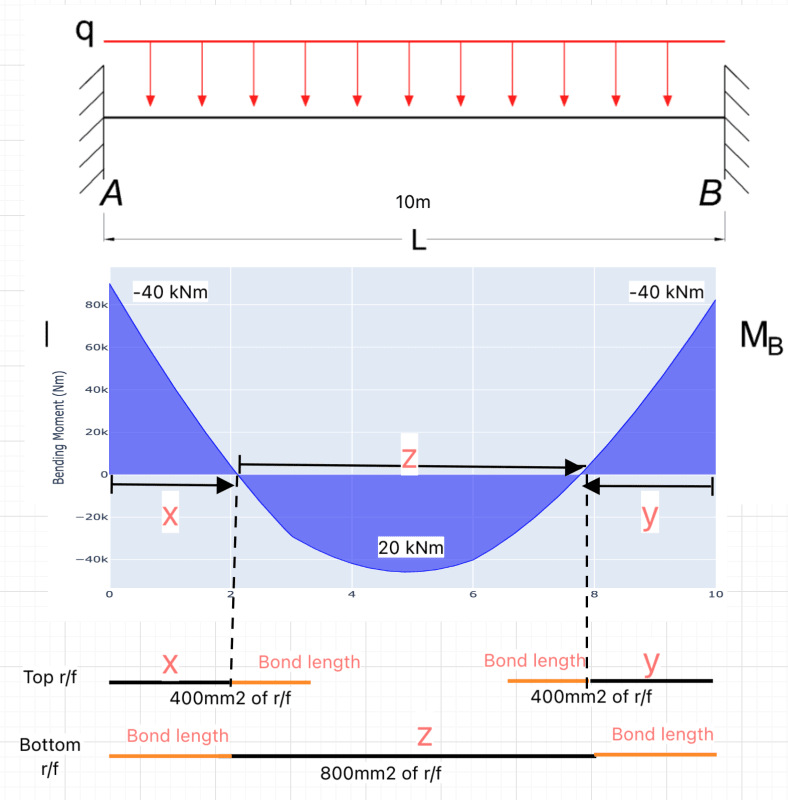
I have calculated the following for a slab. Obtained the area of steel required in accordance with the eurocode2.
It has fixed end supports.
Compression r/f were not needed. The top reinforcement shown below are for the hogging moment.
I have calculated shear r/f needed as well, but didn't include in the figure below.
The following were calculated by considering the slab is "simply supported" for the easiness of calculation (Although it has fixed ends in real)
For 20 kNm moment --> 400 mm2 of steel
For 40 kNm moment --> 800 mm2 of steel
What I'm not aware is how to place these bars.
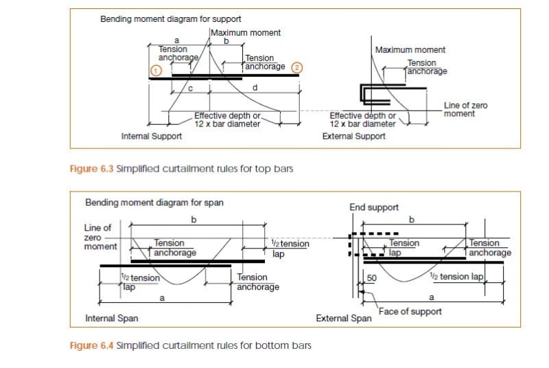
I noticed the Eurocode states some of the bar detailing in "clause 8.7". However, I didn't notice the way it should be placed in the slab, especially for the top reinforcement (For 'hogging' moment).
I noticed there's a 'hogging' moment at the ends because of the fixed end supports. So I'm bit unsure how to place bars.
So I assume the following is the way it should be placed.
1. Please confirm if it's the correct way to place the bars shown in figure below.
2. Please let me know how to find the 'X' distance, so I can determine the length needed for the top reinforcement bar.
3. Below is for a slab, however, I'm wondering if this is the same way to place bars for the beams as well.


