Continue to Site

Eng-Tips is the largest engineering community on the Internet

Intelligent Work Forums for Engineering Professionals

  • Congratulations SSS148 on being selected by the Eng-Tips community for having the most helpful posts in the forums last week. Way to Go!

Base Plate Design Guide 1 2

Status
Not open for further replies.

SALTRAM4567777

Structural
Aug 11, 2020
90
Hi!
I want to know that we follow Yield Line theory for End Plates(DG 16) but when we deal with Base Plates we take cantilever bending.Why?
 
Replies continue below

Recommended for you

I am not familiar with yield line theory, but seems there is nothing wrong if you know how to use it to design the base plate, which might yield a more flexible plate. A good question for AISC fellows though.
 
Yield line is an upper bound theory and cantilever bending is lower bound. Connection of columns to foundations is typically a VERY critical connection with little to no redundancy. As a result, the more conservative design approach is employed.

This is a guess. I could way off, but it makes sense to me.
 
I am not familiar with yield line theory.

The best example for yield line theory is a beam with fixed end moments. Elastically, failure occurs when the end span moment of wl^2/12 occurs. The beam can be safely loaded beyond this until the end span moment reaches the mid span moment. This occurs at wl^2/16. This added load capacity can be used for design. There is also an increase with the elastic secion modulus (Sx) providing the limiting moment. With plastic design, the secion modulus increases to the plastic section modulus (Zx). This gives a further increase in load carrying capacity of about 15%. This is normally called the 'shape factor'.

With steel plate, where there is a uniform thickness, the shape factor is 50%, ie. the Zx/Sx is 1.5, so there is a significant increase. I've used plastic design for about 50 years, and it's great. Usually energy methods are used to determine the plastic moment failure pattern. Pattern loading due to the failure loading, virtually disappears. Deflection is about 1/3 of simple span construction as a rough guide.

I've used plastic design for nearly 50 years and it's great. With large warehouse type buildings, there can be a significant savings in both material and design time. The 400,000 sq.ft. Vista Cargo building outside of Toronto was done using plastic design... the first time this was used by the firm I was working for and there was an estimated savings of nearly 4 lbs/ft^2 for steel framing and I had nearly 1000 hours of budget left over (budget estimate, IMHO, was too high), but the firm was sold on plastic design.

Dik
 
dik,

I learnt yield design at work, but only used once to verify the strength of an existing building. It was a breeze for checking, but I think there are more to it when design. Do use quite a lot for redistribution of moment in reinforced concrete design though.
 
Thanks Dik and pham Eng!
It makes sense, they might have adopted a conservative design approach for base plates .Maybe this is the reason they don't check for prying action in Base Plates as they behave as rigid.
Can you please explain me about lower bound theory and upper bound theory.I know the theory but I wanted it to be in much sinple words.I would really appreciate if you can explain with a example
 
Dik I think you're talking about plastic design. Not yield line theory of plates like the OP is asking about.

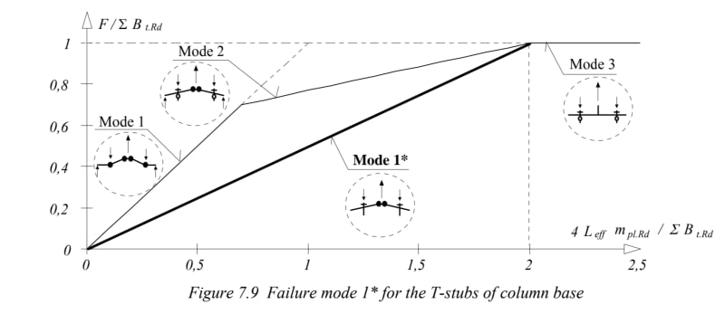
Sammy, DG1 & 16 are fairly old methods these days, there is a lot more recent advice coming out of the UK and Europe. They use yield line theory looking at multiple patterns taking the most critical pattern, converting it to an equivalent T stub of Leff length. Leff is equivalent to Y. DG16 just looks at a single pattern which may or may not be the critical one.

Check out SCI guidance in P398, this is considered more state of the art and is codified in eurocodes.

Nothing wrong with DG16 methods as long as you stick to the limitations on setout. P398 will allow you far more flexibility to assess configurations that won't conform to DG16 configurations including baseplates (there's an entire section on this).
 
The reason they don't check prying on baseplates is that the concrete in bearing out on the edge of the plate often will crush.

See screenshot below, they are basically saying we aren't sure if we can rely on the prying. Therefore let's assume a straight response called mode 1/2 (just cantilever action, no prying) to the start of mode 3 (which is failure in the bolts) in European nomenclature.

20200816_084537_gefjtl.jpg


Edit - screenshot from "Design Of Structural Connections To Eurocode 3 - Frequently Asked Questions"
 
Lower bound theorem
If a set internal forces is identified which are in equilibrium with the applied load on the structure and the yield criterion is not violated then the corresponding applied load is less than or equal to the collapse load"
That is to say, when looking at a set of internal forces due to certain applied load, the system can be shown to be in equilibrium and the yield stress is not exceeded, then the system will not fail.

Upper bound theorem
If a set of internal forces is identified which gives a collapse mechanism then the corresponding applied load is greater than or equal to the true collapse load"
That is to say, when looking at a set of internal forces due to certain applied load, and ensuring they are less than the capacity based on a certain collapse mechanism, then the system will not fail under than collapse mechanism. However, another collapse mechanism may exist which will results in a lower capacity, meaning the same applied load may cause failure.

Source: Analytical Modelling of Structural Systems by I.A. MacLeod (1990)
 
Because yield line theory is an upper bound approach you need to do a fairly good job of predicting the actual mechanism that forms. Otherwise you are potentially over estimating the capacity.

A lower bound answer is conservative, and upper bound is potentially unconservative. You can lower the degree of unconservatism in terms of using an upper bound approach like yield line theory by investigated sufficient numbers of possible failure mechanisms to ensure you have the one with the lowest capacity. If you were to choose a non sensical pattern and calculate a capacity. Then this is an upper bound on the true capacity. It isn't the true capacity, but true capacity must be lower, this is where the term upper bound comes from.

At the true capacity/actual failure, the upper and lower bound answers are one in the same.
 
Thankyou Agent666!
I will go through Euro Codes and get back to you again if I have any doubts.
 
I'm not sure how I feel about ignoring prying action in base plates.

If you play around with the Profis full-blown version, prying action makes a huge difference in the bolt forces (i.e. the bolt forces get much larger with prying action). It may be conservative for the plate, but not the bolts.

It sort of makes a mockery of the arduous calculations of ACI's appendix D if one doesn't know within plus or minus 50 per cent what the bolt forces really are.
 
The prying actions cancel out the additional anchor force as far as the concrete is concerned, or is that not a safe assumption?
 
@JLNJ
If you base Plate is Rigid then Prying action is not a problem for you. You can simply ignore it and most of the codes somehow result in Rigid Ones so you should not worry.
 
Profis models the actual rigidity of base plates, or, rather, it CAN, if you toggle it on.

The differences between rigid and non-rigid are so great that it has to give one pause.

@steve49 - no, the prying action does not cancel out the additional anchor force, it causes it.

I don’t see the forces being large enough to crush the concrete, either.
 
Also I am confused as Agent 666 said that lower bound is conservative and upper bound may be unconservative if not done properly.Tgen how can they result in same answers as Agent 666 said
 
I was thinking of the cone-type failures where the plate is pushing against the concrete to generate the prying force, and therefore stabilising the cone (reducing the nett pull-out force back to the un-pried magnitude). Anchor bond to the concrete would still need to include the prying component.
 
As per DG 1 they have mentioned ome point,if anyone can clarify"Prying forces in anchor rods are typically neglected. This
is usually justified when the base plate thickness is calculat-
ed assuming cantilever bending about the web and/or flange
of the column section (as described in Step 3 below), and be-
cause the length of the rods result in larger deflections
than
for steel to steel connections. The procedure to determine
the required size of the anchor rods is discussed in Section
3.2.1 below.
 
Sammy, the true capacity will be >= a lower bound calculation. The true capacity will be <= an upper bound calculation. If upper bound = lower bound, it follows that the true capacity has been found.
 
@steve So how can we say that canfilever bending is conservative if in my case tge lower bound calculation is equal to upper bound .I will end up with a flexible plate and I have to check for prying which AISC DG1 is telling not to check
 
Status
Not open for further replies.

Part and Inventory Search

Sponsor