Continue to Site

Eng-Tips is the largest engineering community on the Internet

Intelligent Work Forums for Engineering Professionals

  • Congratulations KootK on being selected by the Eng-Tips community for having the most helpful posts in the forums last week. Way to Go!

Base Plate (Single Line Bolts) 1

Status
Not open for further replies.

tristan861

Structural
Sep 14, 2015
77
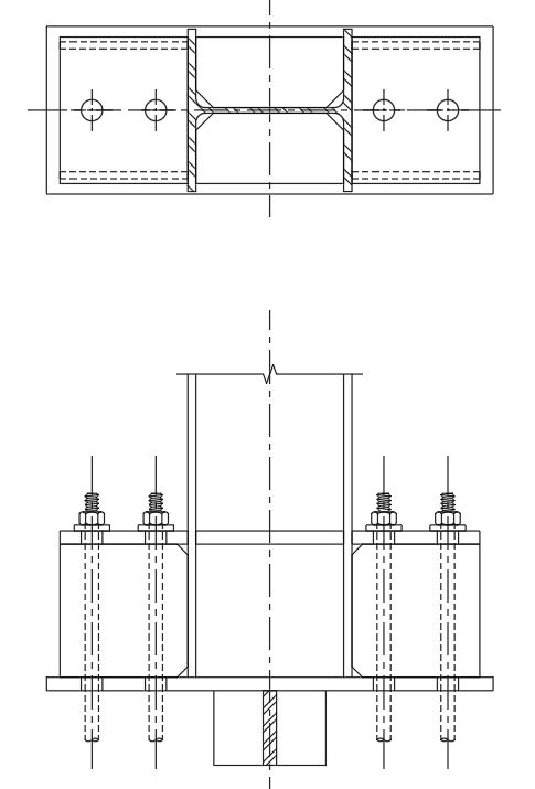
I have this limited RC wall (AROUND 8 inch width). Base plate with post installed epoxy anchors size 7/8''. My question is can I use this single line bolt layout to achieve the minimum edge distance between the concrete edge and anchor? knowing that it's a fixed base plate in major axis with 400 Kips.in
 
 https://files.engineering.com/getfile.aspx?folder=d91753a9-40a5-4a8a-ade4-ee6f8015e8c5&file=Image.jpg
Replies continue below

Recommended for you

Sure, if the numbers work, why not? Obviously, for both strong axis moments and weak axis moments (construction loads), you need to be realistic in assessing how much load will make its way out to the outside anchors.
 
It should work if the column does not require fixity at the base. But why mix concrete structure with steel members?
 
retired13 said:
But why mix concrete structure with steel members?

Better question - why not? After all, coordinating the onsite casting of steel foundations can be a bit tricky.
 
It may work, but the outer anchor rods won't be very effective unless you provide a very stiff base plate. If that was my design, and there is no way to make it work with two anchor rods, I would use a base chair type connection (see attachment bellow).

Base_plate_ydlspq.jpg
 
pham,

I don't think you can convince me using the excuse provided, the mix create more headaches than not. Simply put, you will need to coordinate 2 trades earlier on the project. A concrete column here, the problem is gone, and the resulting structure will be much stronger.
 
Please ignore the shear lug in the detail I just suggested.
 
retired - my comment was more than a little tongue-in-cheek. But in all seriousness - mixing of steel and concrete is very frequent and, when used correctly, can achieve more efficient structures and/or satisfy the requirements set forth by the owners and architects determining what these buildings will look like.

At a larger scale, going all concrete may be a great option. Extremely large steel sections can be more difficult to come by without direct mill orders, and so custom form work can represent a savings. But we're talking about an 8" column here. 8" is a bit small for doing much with concrete. If you have 1.5" cover and #3 ties, you've got about a 4" square for your longitudinal bars. Pretty easy to design an 8" steel column that will best that.

Back to the OP's question - I agree that your connection is possible. Not sure about your jurisdiction, but in the states OSHA requires that all column base plates be designed for some minor eccentricity to make sure the erectors can put it together safely. So as long as the connection works out for that construction load, you should fine.
 
Does HILTI's fancy new Finite Element base plate program have the capability to solve this? Haven't used it or even looked into much, but it came to mind when other posters brought up the question of if the force would get out to the outer bolts.


“Any idiot can build a bridge that stands, but it takes an engineer to build a bridge that barely stands.”
 
MegaStructures said:
Does HILTI's fancy new Finite Element base plate program have the capability to solve this?

Yes, I think it does. However, I think you will find that a quite thick base plate is needed for the connection to work properly.
 
In either direction, a continuous concrete wall is stronger. Is this a corner column to be separated from the concrete wall? If no separation, are you using the flange as formwork? You can dowel the steel column to the concrete wall using studs though.
 
retired13:

This is a continuous RC wall, and this column supports a cantilever steel canopy.

Kootk / PROYOCTOR /PHAMeng /MEGAstructures:

I used RAM Connnection to check the stresses distribution on the anchors and 4 anchors will do. I use 1 1/8 in plate thk.
 
tristan861 said:
I used RAM Connnection to check the stresses distribution on the anchors and 4 anchors will do. I use 1 1/8 in plate thk.

RAM Connection uses a rigid base plate model for determining the internal force distribution. So for this base plate, you won't get a realistic or accurate enough anchor rod force distribution using RAM Connection unless you provide a fairly rigid base plate. I don't think a 1-1/8" thick base plate is rigid enough to assume a rigid plate behavior. Therefore, in my opinion, you should analyze the base plate and anchor rods using a design model that takes into account the base plate flexibility (e.g., using a finite element analysis model) or provide a detail that ensures sufficient bending stiffness.

 
It should work if the column does not require fixity at the base. But why mix concrete structure with steel members?
Clearly noted in the OP's question is that they require base fixity, stick to the actual problem here.

I don't think you can convince me using the excuse provided, the mix create more headaches than not. Simply put, you will need to coordinate 2 trades earlier on the project. A concrete column here, the problem is gone, and the resulting structure will be much stronger.

How about you just stick to the problem, instead of offering opinions that do nothing to contribute to the solving of the problem presented. Telling the OP to change it to concrete does nothing to contribute to the conversation.


I agree with Proyector, definitely need some effective way (i.e. stiff) to engage the outer bolts, without this stiff load path inner bolts only resolve the tension inferred from the base moment. You will not get a realistic distribution of force with any rigid baseplate assumption in this configuration, end of storey.

Most suppliers of post installed anchors have software, and almost universally they utilise this assumption for distributing the moment. Hilti (if you pay for their profis engineering suite) are the only exception I can think of which uses an FEM method to account for the baseplate flexibility and resultant prying forces and realistic bearing under the baseplate.

Working it out by hand and assuming your compression force under the compression flange, and an elastic triangular based force distribution between two anchors on tension face is the way to go. Unfortunately the rigid baseplate assumption will place the compression zone right at the end of the plate, and maybe depending on magnitude of loads all 4 bolts could be in tension. This is very unrealistic, but people seem to believe it because it came out of some reputable software.....

 
Agent, why do you adopt triangular distribution for the tension anchors if you don't believe the plate is rigid?
 
Sorry, I meant if it was stiffened sufficiently to achieve this assumption because I'd imagine one bolt in tension wouldn't cut it. I guess the important distinction between what your black box software solution is giving you and what might more realistically occur is the difference in location for the compression force. Of course stiffeners may also move the compression force towards the edge of the plate with bearing concentrated under any stiffeners provided the are designed to transfer loads to this location.

Otherwise I'd just assume one bolt is taking the tension with a leverarm from the first bolt to the compression flange if we are talking one flat plate. Generally this lever arm will be quite a bit less than assumed with the rigid plate behaviour output from software where 3 or 4 bolts would have a triangular distribution going on.
 
retired13 said:
It should work if the column does not require fixity at the base. But why mix concrete structure with steel members?

Just out of curiosity, is that a serious question? Do you design ONLY concrete structures, strictly? If you have ever designed anything with a piece of steel in it, then you have "mixed trades".

OP, if you're in the US, OSHA requires any 'column', which is any vertical steel member weighing more than 300lbs, to have 4 or more anchor bolts, and must be able to resist the moment created by a 250lb load acting 18" away from the center of the column in any direction - that is an iron worker climbing on the column (best if you double check me on those numbers). Otherwise, a 'post' (less than 300lbs) is only required to have 2 anchors (or 1, i guess..?). My firm regularly specs this type of baseplate, and we also spec standard 2x2 anchor layout baseplates even when bearing on an 8" wall (i personally don't use that detail...). But it gets around the issue of the 4 anchorbolt thing when you have limited space.

HILTI's new CBFEM software will indeed check this (non-triangular/non-rigid) condition. I guess you could do it by hand too, if you reaaaaaly need to. Or, just put in a pier if it's going to keep you up at night.
 
dold said:
Just out of curiosity, is that a serious question?

Surely is. There is an 8" concrete wall nearby, and for reason unknown, it seems OP has selected a steel column that matches the wall thickness. I am looking the possibility to utilize the wall, which is much stiffer, and could eliminate the headache he has. But looks like there are other reasons that prevented him from doing that.
 
Status
Not open for further replies.

Part and Inventory Search

Sponsor