Eng-Tips is the largest engineering community on the Internet

Intelligent Work Forums for Engineering Professionals

  • Congratulations waross on being selected by the Tek-Tips community for having the most helpful posts in the forums last week. Way to Go!

Baseplate bending line for thickness determination 5

Status
Not open for further replies.

steel_plate_arch

Civil/Environmental
Jun 19, 2020
4
0
0
US
Hello,

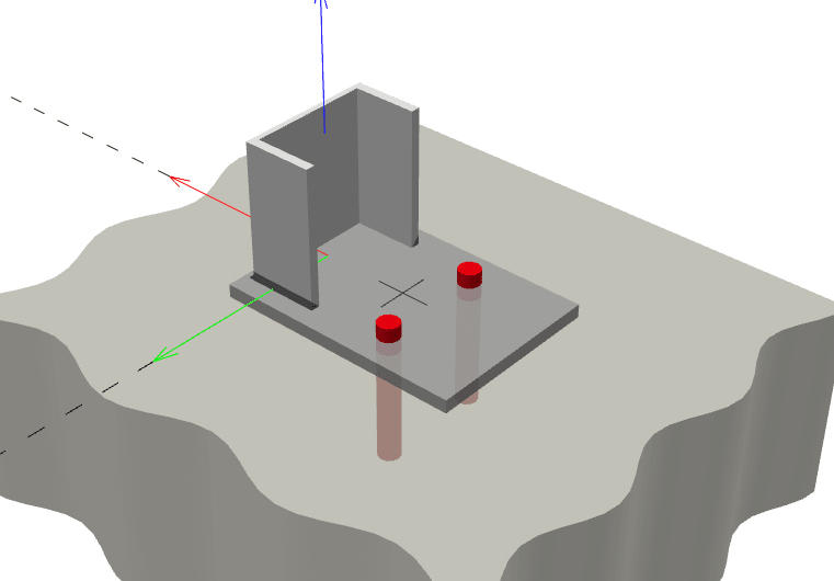
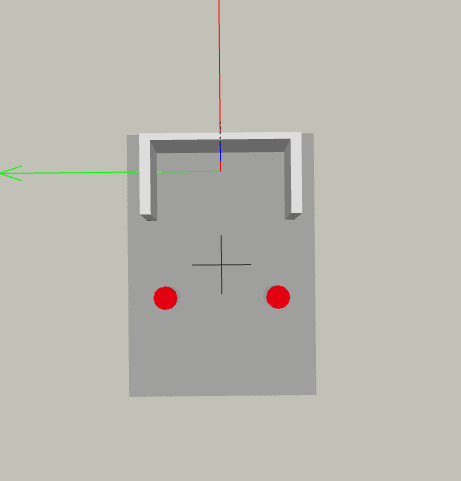
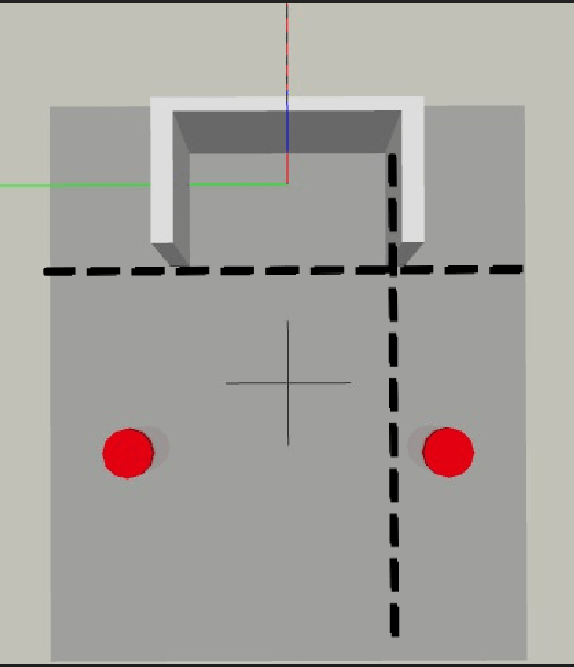
How exactly do I calculate the effective bending line on a base plate like shown below?
I've read that there are 45 degree projection lines that comes from the bolts. What about the farther bolt from the bend line? Is that one also projecting and therefore causes a larger line?

Visually I am having trouble determining how this bending line comes out to be. I've seen in another eng-tips post that also mentions including the perpendicular distance as well, so not sure about that one.

Hope someone can point me in right direction.Thanks.

Capture2_mxgech.png

Capture1_v2cuhy.png

Capture4_nojlap.png
 
Replies continue below

Recommended for you

The controlling loads are going to be the axial load on the channel, but it can be either in tension or compression.

In tension typically about 2 kips and in compression it varies a lot so about 10 - 20 kips or so.

 
The bolts are only there for stability in compression, so that's not a concern. No matter how thick your baseplate is its going to be essentially centered under the column.

In tension, I would be using prying equations, not typical baseplate equations.
 
For the uplift, I would use Yield Line Theory. My belief is that the critical yield lines are shown below, but you could experiment to see if you can find a more critical one. So the base plate must be designed for a moment of Pa/2 where P is the uplift (2000# in this case). It is assumed that the channel is capable of providing sufficient moment resistance.

Capture_nb5no2.jpg
 
Interesting, yield line theory isn't typically used for baseplates in my experience - though this has always bothered me to some degree. If the compression block can resist the prying force it has always seemed to be a valid approach. I'd be interested to hear if some folks are using YLA for their base plate design. I probably wouldn't use the prying equations directly from the SM (though they are also derived from yield line theory) as they also use the tensile strength rather than yield as it correlated better with testing.

I agree with BA on where the yield line would be based on this geometry, however if you wanted a simple and conservative approach consistent with AISC DG1 that would not have to account for prying, I would design the plate for a moment of P*(a+0.1*b_f), referring to BA's sketch. The 10% of the flange width added to the moment arm accounts for some variation in where the section provides that flexural resistance.
 
I would not argue with adding 10% of the flange width, but the expression for moment should be (P/2)*(a+0.1*b_f) because there are two yield lines, not just one.
 
BA - I agree there are the two yield lines if you are taking a YLA approach and allowing the plate to hinge near the section. Typical baseplate design methodology in my experience (specifically per AISC Design Guide 1) is to only allow for the formation of the first hinge. Again, I've always been a bit bothered by this approach as it leads to excessively thick plates, but it does not require considering any prying forces in the anchors or in the concrete. Also, people are pretty used to certain size base plate thicknesses at this point, so I just keep the status quo when it comes to base plates. For steel to steel connections I'll use YLA frequently. But again, would love to know if others are utilizing YLA for their baseplate designs.
 
Flotsam7018 said:
Typical baseplate design methodology in my experience (specifically per AISC Design Guide 1) is to only allow for the formation of the first hinge.

I'm not familiar with the AISC Design Guide in respect to base plate design, so I will have to check it out when I have time. At a glance, it seems to be conservative. But I cannot quibble about using thick base plates. I don't like to see base plates 3/8" thick. They tend to curl with the heat of welding. I prefer to use a minimum base plate thickness of 5/8" or even 3/4", which may seem a bit arbitrary, but over many years of practice, I can't recall anyone objecting.
 
Don't you need the column to be stiff to develop the second yield line near the channel toes? Obviously, the channel is not stiff in the weak axis.

For a singular base plate, I'd probably consider prying about the free edge and look at flexure at the bolt line for the design of the plate.
 
I like BAretired's approach on this one.

JLNJ said:
Don't you need the column to be stiff to develop the second yield line near the channel toes?

Stiffness will certainly help things along. However:

1) Strength wise, I think that the flexural capacity of the channel in weak axis only needs to meet or exceed that of the base plate.

2) Tension tends to stiffen a cross section against flexure.

3) I believe that the second yield line against the channel flanges would eventually materialize so long as you have [1].

Flotsam7018 said:
...however if you wanted a simple and conservative approach consistent with AISC DG1 that would not have to account for prying, I would design the plate for a moment of P*(a+0.1*b_f)

I feel it is that approach that is highly dependent on column stiffness. If the column does not offer significant rotational restraint to the joint, you will have significant prying and your bolts may be overloaded prematurely if the design was based on not having any prying.


I would point at the AISC design guide for base plates. They have a similar diagram as I recall for bending induced by bolt tension.

It also appears you have a column as defined by OSHA, based on the loads, which would typically require 4 bolts.

If you put in four bolts, the yield line should get clearer. You aren't legally required to do more with less all the time.

Regards,
Brian
 
In the UK, we would mot likely adopt a T-stub approach, which is basically a yield line approach. An example of considered yield lines is below. It would probably need to be adjusted for your application:

end-plate_yil9em.png
 
With a simple layout like this, I'm with BARetired and KootK.

But, if the base plate were to bend in the OTHER direction, then I think it would get interesting. But, I would still use yield line theory.
 
I often use a FE model with an elastic-perfectly-plastic material for the plate elements. I always verify that it is giving a sensible answer by checking a yield line model, but I've found the FE model will usually come up with a more critical yield line arrangement than I can figure out by hand.

One complication I used to run into often is that the FE model will often predict pretty significant in-plane forces in the baseplate as it deforms, which adds a lot to the apparent capacity (i.e. the baseplate begins to act partly in tension). I believe it is probably a real effect, especially for thinner baseplates that will deform significantly before settling into a failure mechanism. But it can be easily solved by switching off the nonlinear geometry option in the model.
 
KootK said:
1) Strength wise, I think that the flexural capacity of the channel in weak axis only needs to meet or exceed that of the base plate.

I see it as the channel and the weld group need to resist the total moment, let's say P*(a+e) where e is the additional distance from the yield line to the centroid. Fundamentally I don't see a difference between this scenario and the standard prying model (except the additional eccentricity) where the first hinge forms at the distance a and only once this hinge forms are the additional prying forces necessary for equilibrium, sketch below from the Carlo Lini article that explains better than I can here for the case without prying:

Prying_Lini_cyvyji.jpg


I am not against considering the additional yield line at the bolt line and the resulting prying forces, I just typically have found people are weary of using YLA on base plates - but apparently not this crowd, which is encouraging.
 
In Figure 1 the applied and resisting forces are offset. How is the moment accounted for? In a tee shape, symmetry provides the balance. In a single angle some other mechanism must form (unless the angle translates and the two forces line up).
 
It looks like this is modelled in Hilti Profis. If you use the FEM baseplate option and increase the loads beyond yield, the output should show you where the yield lines are forming.
 
With a theoretical pin at B, the moment in channel and plate are shown below.

If the channel rotates, which it will, the pin at B will move left, so that Mplate is increased. The elastic moments are dependent on the relative stiffness of the plate and channel. If the plate is made much stiffer than the channel, the plate will take a higher share of the total moment P(x+a). For the small cost involved, I would not be averse to designing the plate for the total moment.

Capture_dyqlcy.jpg
 
BA - I believe we're on the same page, I'm just making the case for not allowing the hinge to form at B as in your sketch and prevent prying forces from developing. That being said, if you do allow the hinge at B you need to account for the additional prying force in the bolt.

JLNJ, this previous thread goes into depth on this topic: Link
 
Status
Not open for further replies.
Back
Top