Continue to Site

Eng-Tips is the largest engineering community on the Internet

Intelligent Work Forums for Engineering Professionals

  • Congratulations GregLocock on being selected by the Eng-Tips community for having the most helpful posts in the forums last week. Way to Go!

Basic beam structural analysis - Hand Calc and Strand7 2

Status
Not open for further replies.

rpand4

Civil/Environmental
Jun 20, 2011
21
Hi Team,

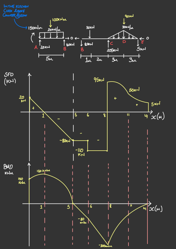
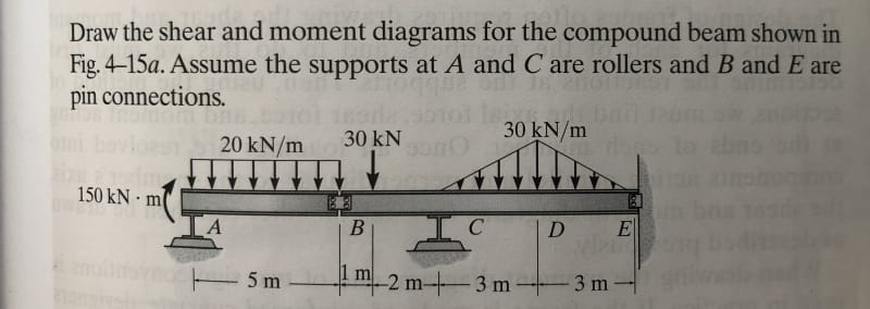
I have just been brushing up on my structural analysis. I picked an example problem from a text book to draw a BMD and SFD.

This is the problem I picked:
IMG_0623_bk3ogt.jpg


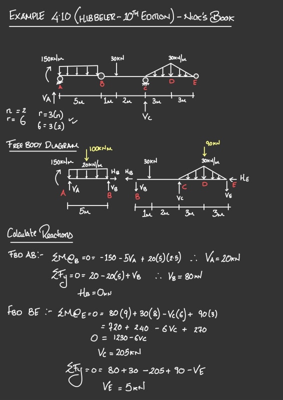
I undertook a hand calculation as follows:
IMG_0190_xacfdv.jpg
IMG_0191_eyc7cb.jpg


I am confident the solution is correct but thought of double checking it in a modelling software (Strand7). I have not used strand7 before and its a bit of a learning curve. I have used SpaceGass in the past but I don't have access to that software.

I modelled the problem like this:

End_Release_Strand7_ocxj6t.png


When I ran it I got an error - "Singular Matrix". I knew immediately that the issue must be the two ends that I have released rotationally. I released them cause I wanted to mimic a pin connection as the question asks. If I remove the rotational release, the model works and produces an output. So I know for sure it is that pin connection that is causing the analysis to halt.

What am I doing wrong in the model? The way I have modelled it with that pin connection is probably forming a mechanism.

Any thoughts and advice please as to where I could be going wrong?
 
Replies continue below

Recommended for you

Checked in Spacegass. Hand calcs look spot-on mate. Can't tell from your picture, but have you tried restraining rotation at the support about the X-axis? i.e. restraining from rotation out-of-plane?

bmd_bgd7zh.png
sfd_st8zk8.png
 
is your FE solution spinning about the axis of the beam ?

another day in paradise, or is paradise one day closer ?
 
StrucPatholgst said:
ClearCalcs is a lot more user friendly. Might want to try that.

Thank you for your response. You mean detailing out the BMD and SFD calcs in more detail (method of sections etc)?
 
Steve95 said:
Checked in Spacegass. Hand calcs look spot-on mate. Can't tell from your picture, but have you tried restraining rotation at the support about the X-axis? i.e. restraining from rotation out-of-plane?

Ah! Thanks for double checking. Reassured that I got it right. I def have restrained the out of plane rotation about the x-axis.
 
rb1957 said:
is your FE solution spinning about the axis of the beam ?

If I remove the rotational release on either side of node 2 then the solution works. However to mimic the pin connection at node 2 I released the rotation around the z-axis. When I run it, the solver says the following:

"Global stiffness matrix singular at equation 26 - Pivot = 0.000000E+00 (Node 2 RZ)."

So its definitely not liking the release about the Z-Axis. I can't work out why.

I have added a link for my strand7 file if anyone has some spare time to have a look at it and advice

 
 https://files.engineering.com/getfile.aspx?folder=eaa99ec2-5cbd-4286-8409-36050d83aae2&file=Mesh2old.st7
Are you releasing both beams at Node B? You can't do that because the node would be free to rotate. Even though nodes don't exist in real structures, they have to be restrained in the model, so just release one beam or the other.
 
steveh49 said:
Are you releasing both beams at Node B? You can't do that because the node would be free to rotate. Even though nodes don't exist in real structures, they have to be restrained in the model, so just release one beam or the other.

You solved it! Yeah I was releasing both beams on either side of B. I restrained one side and released the opposite side and it solved the issue. I got the same BMD and SFD as my hand calc.

Now I understand why we can't release both sides - because the node will be free to rotate and the whole thing would form a mechanism. But in reality wouldn't you expect that the beams on either side of pin connection at B would be able to rotate?

Thank you very much for pointing me in the right direction.
 
It's a by-product of the stiffness method. Displacement and rotation of the nodes are calculated by finding a position that satisfies all the member stiffnesses simultaneously. If there's no restraint from members, stiffness of the node is zero and its position (rotation angle) can't be calculated = no solution.

Some software will try to fix this by applying a very weak spring to unstable nodes. If the node rotation is still small (basically infinitesimal) then the instability wasn't critical. Maybe Space Gass does that because it looks as though both beams were released in that model too.
 
steveh49 beat me to it.

Note that the ends of both beams are free to rotate when one has a released end restraint, because the other beam has nothing restraining rotation.

Also for a 2D analysis go to Cases-Freedom and set the freedom conditions to 2D beam XY (or as appropriate for coordinate system), then you don't have to worry about restraining Z deflections, or rotations about X and Y.

Regarding ease of use, as a full functioning FEA package Strand7 certainly has a lot to learn, but once you learn the basics it is very quick and easy to set up simple models like these, and extract the results.

Doug Jenkins
Interactive Design Services
 
IDS said:
Note that the ends of both beams are free to rotate when one has a released end restraint, because the other beam has nothing restraining rotation.

...that makes total sense. I was so engrossed in the problem that I didn't realise it! Ah learned something new today. Awesome! Thanks
 
Status
Not open for further replies.

Part and Inventory Search

Sponsor