Continue to Site

Eng-Tips is the largest engineering community on the Internet

Intelligent Work Forums for Engineering Professionals

  • Congratulations IDS on being selected by the Eng-Tips community for having the most helpful posts in the forums last week. Way to Go!

Beam Capacity - Question in Principle 2

Status
Not open for further replies.

DavAD

Structural
Nov 20, 2017
8
Dear all,

I have attached two scenarios of a reinforced concrete beam carrying a horizontal slab.


In principle, would you say that in Scenario B, the beam has a higher load capacity than in Scenario A, considering that the whole depth is beneath the actual slab load, whereas in the other case (A) the load is 'hanging' at the bottom of the beam.
P.S. The beam has in both cases been designed for the slab load, supported by the beam.

Your comments are greatly appreciated.

Kind Regards
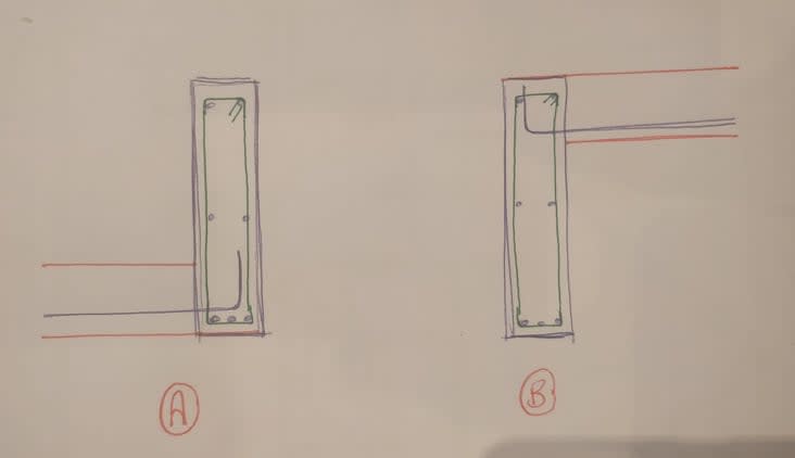
124026642_1069295633514088_5688176462159806784_n_jh16fo.jpg
 
Replies continue below

Recommended for you

Slightly higher beam capacity depending on whether beams are in negative/positive flexure, and only due to the larger effective depth when the slab is in compression (wider compression width and all).
 
There are pros and cons to each case.

Assuming it’s in positive bending, Case A has an advantage that it will pickup slab reo which will add to bending capacity, however case B has a much larger and more stable stress block within the slab. A lot depends on the reo as to which one wins.
 
For top face in compression, in case B, you can engage a portion of the slab in the design, thus increases the compressive area, and increase the lever arm by shifting the natural axis upward.

By the way, for both cases, the slab bars are in the wrong face.
 
Additional considerations:

1) If the beam is very slender, placing the slab where it would brace the compression zone will help to precluded lateral torsional buckling.

2) With regard to stirrup detailing, placing the slab higher on the beam will lower the demand for stirrups and hanger steel. The impact of this would be slight, however, and I'd not consider it a limit on capacity. Rather, just detailing nuances to be sorted.

 
Case B would have higher overall load capacity. Bars should be on the top of slab and hook downward.
 
Dear All,

Thankyou for your feedback.

With regards to reinforcement, the slab is a simply supported slab (supported on two beams), that is why the steel reinforcement is in the bottom, i.e. tension.

Perhaps you thought it is a cantilever slab?
Sorry if i was not clear in my explanation.

Regards

 
With regards to reinforcement, the slab is a simply supported slab (supported on two beams), that is why the steel reinforcement is in the bottom, i.e. tension.

Even with intentional CJ at the beam-slab interface, you are going to see cracks on the top face near the beam. You can do it for case B though, if the slab is cast over the beam without rebars crossing.
 
Agree, even if you design the slab as simply supported you need to provide a nominal reinforcement on top that will ensure shear transfer and allow for a "controlled" rotation.
 
I’ve seen a lot of engineers fail to consider LTB in concrete. You can design the vertical bars to achieve some U-Frame action to resist this, but it requires consideration nonetheless.

For that reason, I’d simply prefer Case B.
 
MIStructE_IRE said:
For that reason, I’d simply prefer Case B.
Could you elaborate why B is better for LTB? I'm a bit confused, I'd expect the load being input at the bottom would stabilize the lateral buckling. What am I missing?
EDIT: Keep in mind we don't know which side is in compression. In fact I would expect that detail A would be applicable to a balcony (cantilever) to ensure that the balcony level is lower than the level of living area, I wouldn't expect to find the detail A in a living area.
 
depending on how you check the capacity option B may not buy you as much extra capacity as you would think:
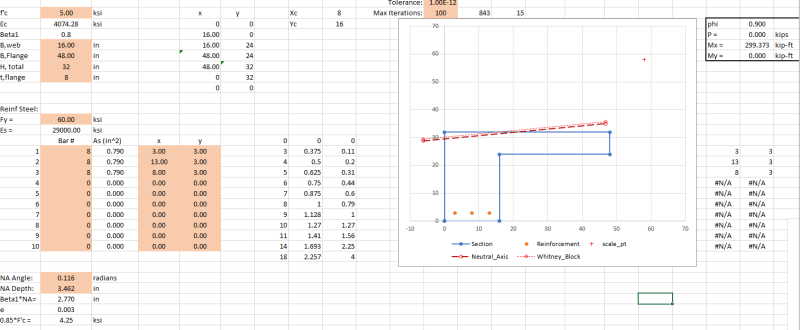
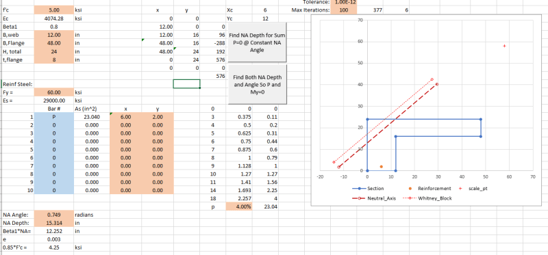
Capacity for pure Mx Bending, section and reinf. should be visible in the screenshot:
L_my_0_lr4fw4.png


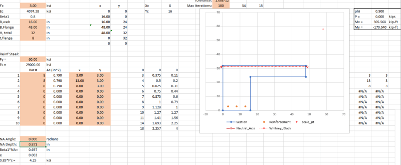
Capacity allowing a non-0 value for My, Neutral Axis Angle = 0:
L_alpha_0_w1gyyf.png


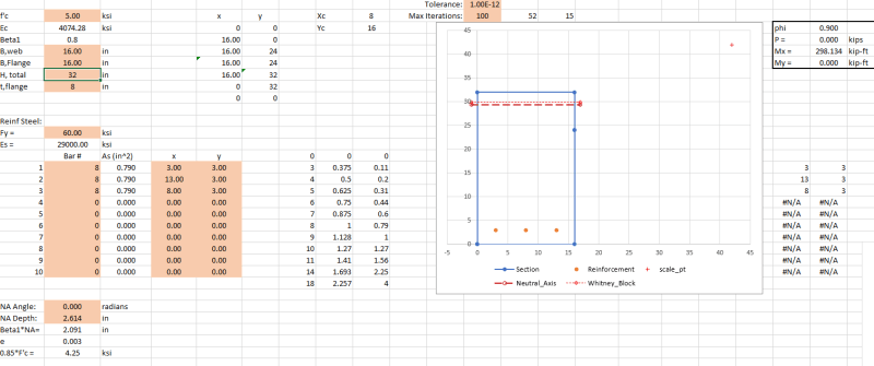
Rectangular Beam Capacity:
rect_oepphf.png


My Personal Open Source Structural Applications:

Open Source Structural GitHub Group:
 
@celt
In your example compression height is about 2,5% of the section height for L section and about 8% for rectangular section. I guess the difference changes when you get closer to 45% of the section in compression.
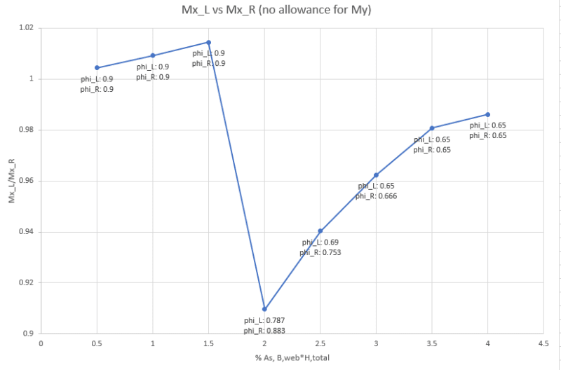
It would be interesting to plot the M_capacity(L section) / M_capacity(rectangular section) versus the percentage of steel.
 
hardbutmild said:
Agree, even if you design the slab as simply supported you need to provide a nominal reinforcement on top that will ensure shear transfer and allow for a "controlled" rotation.

With regard to the detailing, that's the bit that I'd be keeping an eye on. Without the top bars, shear friction goes out the window and you're basically down to just true dowel action in the bars. That can be done but I'd not be taking it for granted without explicit checking.
 
Here is the Spreadsheet: Link

I threw this thing together this morning so it's a bit spartan and the solver that finds both the neutral axis angle and depth may run into some conditions where it doesn't find an answer.

My Personal Open Source Structural Applications:

Open Source Structural GitHub Group:
 
@hardbutmild - since he’s said this is a beam supporting a simply supported slab I’m going to assume the top of the beam is in compression.

As such, it would seem to me best to restrain the compression zone (top) to prevent LTB.
 
Cleaned up the sheet a litte bit.

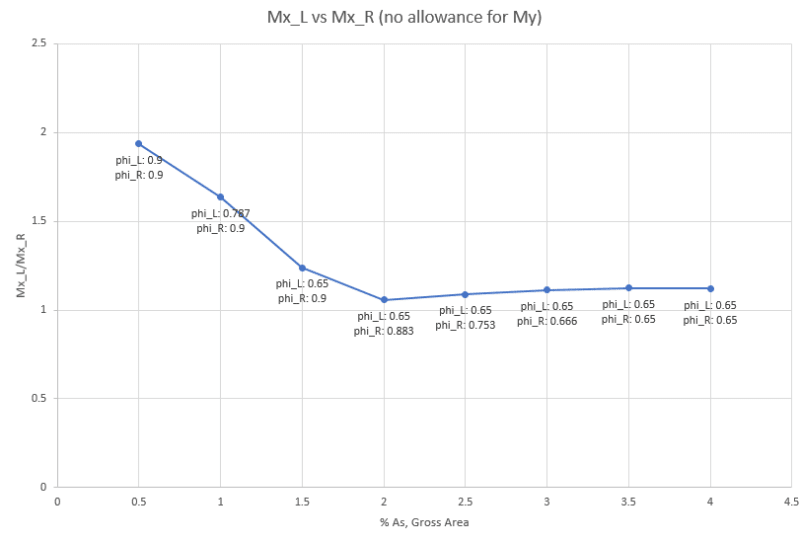
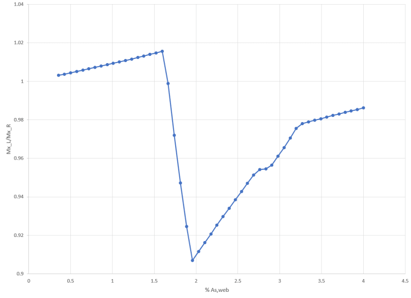
based on ACI %As should be based on B,web * d so the second graph is actually the one to look at, I reset the macro to start at minimum As% and go up to 4% over 50 iterations here is the new resulting chart:
Capture_kr74h0.png


- The steep drop is where phi departs from 0.9 and where the Neutral Axis starts getting steeper for the L to keep the compression block resultant in line with the steel so My remains 0.

- Looking at it this way the bump in capacity doesn't seem to get much above 2%


My Personal Open Source Structural Applications:

Open Source Structural GitHub Group:
 
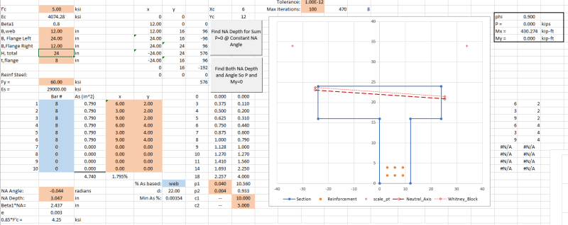
now the sheet can handle asymmetric or symmetric T's. Changed how the shape was generated before B,flange was also the total width now the total width is B,web+B,flange right+B,flange left.

Capture_o2l4ki.png


Version History of the sheet can be seen here: link

Edit: renamed the file to clarify it covers T,L, and Rectangular Sections - Link
New Version History link: link

Edit2: Option to solve for a resultant with the same unit vector as the applied load, allows for a utilization ratio as would be reported by commercial software.

My Personal Open Source Structural Applications:

Open Source Structural GitHub Group:
 
Status
Not open for further replies.

Part and Inventory Search

Sponsor