Continue to Site

Eng-Tips is the largest engineering community on the Internet

Intelligent Work Forums for Engineering Professionals

  • Congratulations KootK on being selected by the Eng-Tips community for having the most helpful posts in the forums last week. Way to Go!

Beam Stability Question 2

Status
Not open for further replies.

XR250

Structural
Jan 30, 2013
5,409
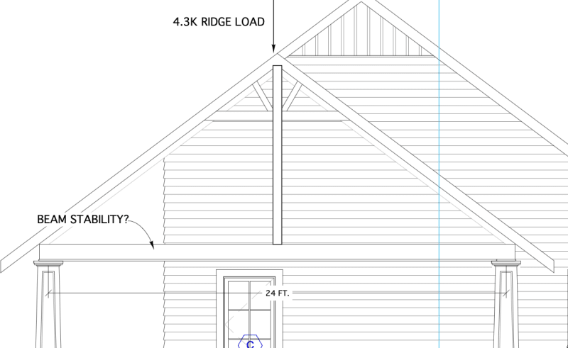
This is a carport project. Besides looking at the NDS equations for beam stability due to the 24 ft. unbraced length and perp. wind load, Is there an added instability due to the column load being applied to the compression flange versus the load being hung from beneath? I imagine I will be adding a girt on top of this beam.

CARPORT_cnalvt.png
 
Replies continue below

Recommended for you

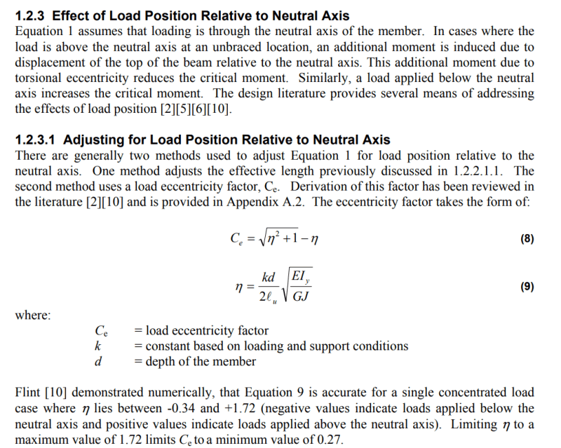
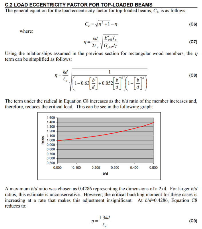
Here's the relevant bit from the link I posted earlier:

Screenshot_2024-10-03_120114_jo6gmv.png
 
Crystal clear like a prism today - the light comes through but is distorted and scattered.

My initial stance was in error. My thinking was along the lines of lexpatrie's, that the NDS covered the situation. So I was trying to clarify that point and the part of the NDS that looks like it covers this condition.

phamENG said:
A column sitting on top of a beam and dependent upon the beam's lateral and torsional stability for its own stability is, however, a different kettle of fish, as you pointed out.

My last statement is a less clear way (when compared to your sketch) of conveying my agreement. The analysis method in the NDS is incorrect for the application for two reasons:

Reason 1 - this is an unbraced beam with a point load above the neutral axis, so the as published equation for l[sub]e[/sub] doesn't work. It can be adjusted per the tech note I posted above and bones reiterated and posted the relevant equations in line (though that tech note leaves a lot to be desired...).

Reason 2 - the column stability is dependent upon the stability of the beam. This is the point you're focusing on, and for good reason, as it is likely to drive the instability of the beam much more than simply applying the load a few inches above the NA.

Now I've expended entirely too much energy arguing with you to convince you that I agree with you. Welcome back!
 
Ah, sorry pham. Completely glossed over your first post with the tech note!
 
No worries. That wasn't intended to a passive aggressive stab at you, either - so sorry if it was taken that way.
 
Not at all, just kicking myself for missing it in the first place then being like “hey guys! hey guys! look what I found” haha
 
There seems to be two distinct failure modes that people are talking about here.

One is the beam’s rotation due to the destabilizing effect of the load being above the neutral axis. For such destabilizing loads, design codes prescribe an additional factor to increase the effective length, which several people above are discussing.

The other issue is the overall lateral translation of the beam and column assembly, where both elements sway laterally together without rotating relative to one another, as shown in Kootk’s first diagram.

The first scenario, beam instability, is more critical, as it results in a significantly greater “effective length” for design purposes.

Is you design the beam effective length as the real length, multiplied by the destabilising load factor, you will cover it.
 
KootK said:
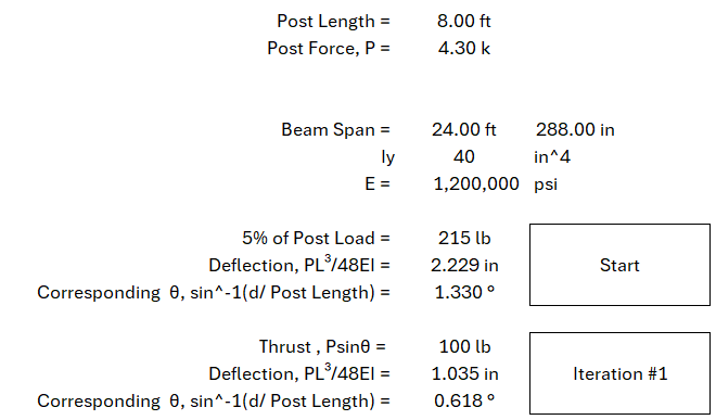
As the post load increases, so will the lateral thrust that it imposes on the beam. The goal is to find that lateral thrust once it's done it's job stabilizing the bottom of the strut.. So another way to describe the iteration is:

1) Guess the angle of the post using an assumed lateral deflection of the beam.

2) Work out the thrust on the beam based on the angle of the post.

I'm having one of those days and I don't know why I'm struggling so much with this iteration.

Is the thrust on the beam=Psinθ, where P is the ORIGINAL post axial force and θ is the angle determined in step 1?

OR

Is the thrust the equivalent x-component force required to create the angle θ... as in the Post load is equal to [(deflection x 48EI)/L³]/sinθ?

Is there an example calculation of this somewhere I can follow along?
 
I came back to take an even more tired look at it... and yep, still not getting it.

For some reason, whenever I iterate my deflection either drops down to zero or keeps exponentially growing.

See below (Note: the Iy and E are just some random numbers I pulled from NDS)

I've clearly misinterpreted what you said.
Screenshot_2024-10-03_230627_mjqydg.png
 
I'm not sure this is a great solution, but you could design a post to beam connection which transfers the load to the neutral axis of the beam. That would at least solve one problem (while perhaps introducing others).
 
Eng16080 said:
'm not sure this is a great solution, but you could design a post to beam connection which transfers the load to the neutral axis of the beam. That would at least solve one problem (while perhaps introducing others).

The same idea had occurred to me. Unfortunately, most practical versions of that that I could conjure up then invited a tension perpendicular to grain / edge distance problem in the connection. And I would consider that to be a much bigger concern than applying load 4" above shear center. Historically, wood construction was mostly about stacking stuff on top of other stuff. And there are good reasons for that.

tomfh said:
The first scenario, beam instability, is more critical, as it results in a significantly greater “effective length” for design purposes.

My intuition is actually the reverse of tomfh's in that:

1) Load 4" above SC on an 8" tall beam doesn't strike me as a big deal and;

2) The global instability thing makes me genuinely twitchy.

I need some numbers to calibrate. I'll try to do something numerical on the global bit before I disappear for another six months. Or maybe StrEng007 will do it for me...

Anybody else want to take up the load above SC thing?
 
StrEng007 said:
For some reason, whenever I iterate my deflection either drops down to zero or keeps exponentially growing.

No time for a detailed check of it just now but what you've done sounds promising. I would expect this:

1) If Iy is too low and it's unstable, deflection grows without bound.

2) If Iy is sufficient it should stabilize on a particular total deflection with the incremental new deflection approaching zero.
 
phamENG said:
A column sitting on top of a beam and dependent upon the beam's lateral and torsional stability for its own stability is, however, a different kettle of fish, as you pointed out.

I see it now. I should have read that more closely. Sorry for having wasted your time needlessly.
 
Without getting too technical, if there's an effective brace on the top flange at the load point on the beam, there's no stability issue. It should also decrease the ℓ[sub]e[/sub] of the beam itself.

I don't quite see how you're going to connect the king post to the beam without at least some measure of rotational restraint in both directions, difficult to quantify, perhaps, but some sort of restraint feels inevitable.

More to the point, the restraint against twist at bearing feels more arbitrary/not there. But this can be handled with blocking or some other restraint. Perhaps a seated connection to the perpendicular framing, then again, water.

(for those with post envy... here's where I got that script ℓ from, it's not my favorite script ℓ, but it will serve for now, -
 
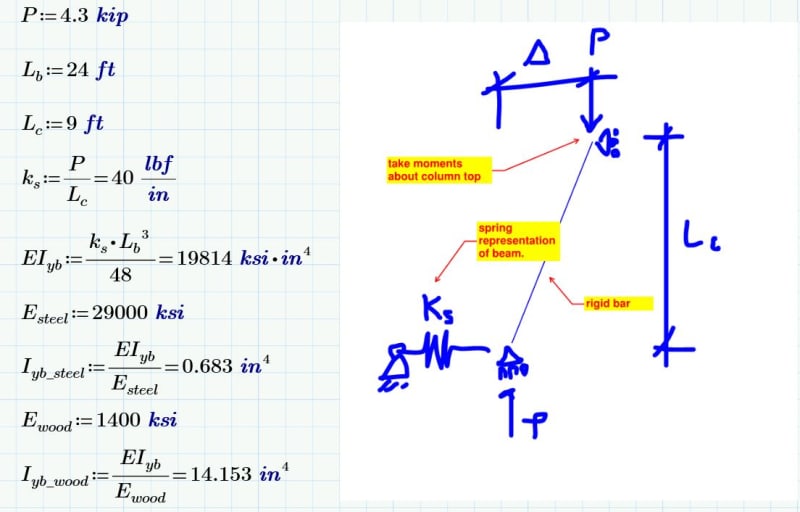
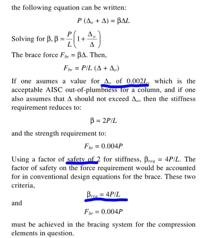
So I slapped together a closed form bifurcation analysis that doesn't include a factor of safety or initial imperfection. That gets me a shockingly low beam stiffness requirement of 40 lb/in at midspan.

Fisher's method includes initial imperfection and a factor of safety of 2. This produces a stiffness requirement 4X mine, so 160 lb/in. Either way, though, the EI requirement of any reasonably sized beam ought to be quite manageable.


c01_hbbd69.jpg


c02_eq7w03.jpg
 
Status
Not open for further replies.

Part and Inventory Search

Sponsor