Continue to Site

Eng-Tips is the largest engineering community on the Internet

Intelligent Work Forums for Engineering Professionals

  • Congratulations pierreick on being selected by the Eng-Tips community for having the most helpful posts in the forums last week. Way to Go!

Beam Stability Question 2

Status
Not open for further replies.

XR250

Structural
Jan 30, 2013
5,760
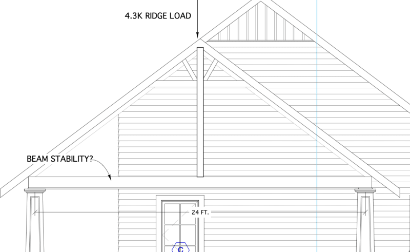
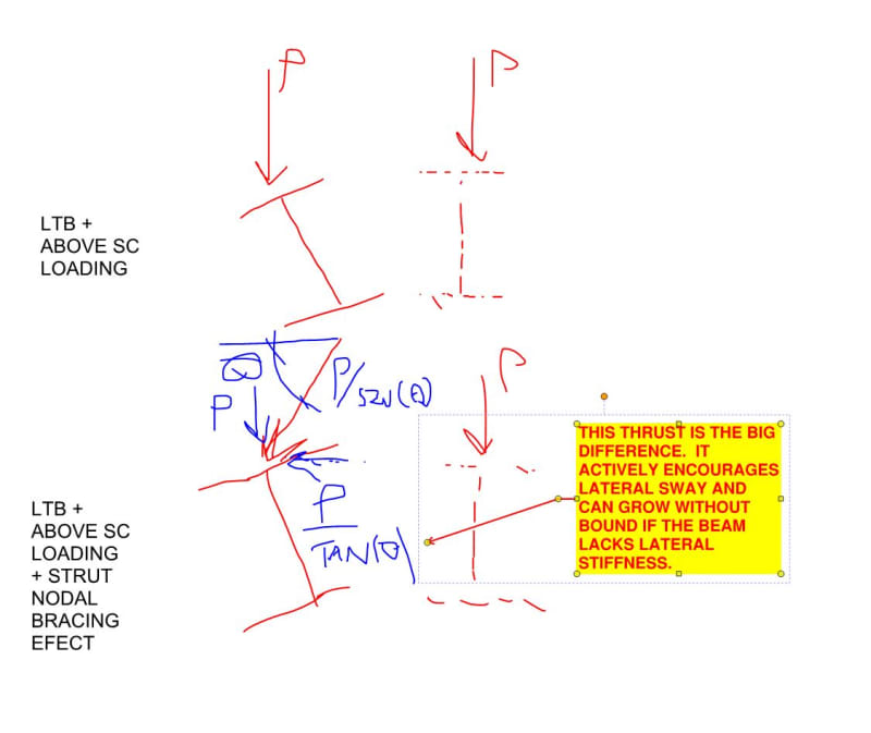
This is a carport project. Besides looking at the NDS equations for beam stability due to the 24 ft. unbraced length and perp. wind load, Is there an added instability due to the column load being applied to the compression flange versus the load being hung from beneath? I imagine I will be adding a girt on top of this beam.

CARPORT_cnalvt.png
 
Replies continue below

Recommended for you

Isn't there a tabulated le for the center point loads in the NDS?

You need lateral stability at the bearing points (and maybe the loading point) but that's kind of a universal requirement in wood design.
 
XR250 said:
Is there an added instability due to the column load being applied to the compression flange versus the load being hung from beneath?

There is, in fact, a very important additional stability demand in my opinion. Good on your for intuiting it. My sketch sucks but I know that you usually don't need much to interpret my ramblings.

It's a version of P-Delta and would tend to induce an instability mode close to pure lateral translation. Highly slender bridge girders do something similar sometimes during erection.

c01_wajct8.jpg
 
You can probably make your beam check out by making it a bit stocky. If not, you might be able to do something like I've shown below where the post braced the beam top. Just gotta make it architecturally palatable somehow.

c01_pfl6yt.jpg
 
Thanks for that. I was thinking of installing an 8" channel on top of the beam to act as a girt or just use a really stocky W8 for the beam. What kind of stiffness would you think I would need to stabilize the P-Delta?
 
Welcome. I'd do some poor man's version of a non-linear analysis by way of iteration. Something like:

1) Apply 5% of the post load as a lateral load.

2) Figure out what lateral deflection #1 gets.

3) Revise the lateral load to match the post angle implied by #2.

4) Return to #2 and keep looping until the deflection stabilizes roughly.

I usually find that these kinds of things stabilize within five iterations if the initial stiffness is anywhere in the ballpark of what you need. Excel makes short work of it.

 
Yes a load that tends to destabilise a beam is worse in regards to buckling than one which doesn't. Most codes have factors to account for this.

Put simply, a load on top tends to make the beam fall over. A load hanging below doesn't.
 
The effective length captures the effect of the support and loading condition (simple span, point load at center) as alluded to by lex, but after some checking it does look like those equations are specifically for loads applied at the neutral axis. So I'm with KootK on this. Some additional P-Delta consideration would be prudent.
 
Thanks. I'll check it out. Welcome back, BTW, KootK
 
If I use an I-beam and a stiff steel king post column, attached sufficiently, wouldn't that mitigate any torsion and just leave me with lateral movement?
 
KootK said:
2) Figure out what lateral deflection #1 gets.

3) Revise the lateral load to match the post angle implied by #2.

You lost me between step 2 and 3. What did you mean?
 
Well the Arch decided no king post so I will be designing the gable as a steel truss which will make my cross piece tension only under gravity loads. Need steel anyway for the support columns due to an overall lack of lateral stability.
 
phanENG said:
The effective length captures the effect of the support and loading condition (simple span, point load at center) as alluded to by lex, but after some checking it does look like those equations are specifically for loads applied at the neutral axis.

I disagree. I feel that no LTB check is likely to capture this unless it's highly contrived to do so. The reason for that is because the issue at play is not really lateral torsional buckling (there is that, in addition). The particular issue involved is really the need for the beam to act as nodal bracing for bottom of the compression post. Similar to Fisher's thing on tension chord bracing.

The need for the beam to brace the bottom of the compression strut creates a separate lateral load that needs to be considered in the biaxial design of the beam. That load needs to be worked out using the beams lateral stiffness as one of the inputs. The iterative procedure that I mentioned earlier is one way to do this. Using the AISC procedure for nodal bracing would be anohter.


Yup. And that would be a fine idea were you not be going in another direction. Although, technically, you still have a similar stabilizing requirement for the bottom chord even when it's at tension member (Fisher's paper again). The tension just improves matters by tending to straighten out what the nodal bracing effect would tend to push out of plane.

c01_orlast.jpg
 
Str007 said:
You lost me between step 2 and 3. What did you mean?

As the post load increases, so will the lateral thrust that it imposes on the beam. The goal is to find that lateral thrust once it's done it's job stabilizing the bottom of the strut.. So another way to describe the iteration is:

1) Guess the angle of the post using an assumed lateral deflection of the beam.

2) Work out the thrust on the beam based on the angle of the post.

3) Revise the lateral deflection of the beam based on the thrust.

4) Revise the angle of the post based on the revised lateral deflection.

5) Revise the thrust on the beam based on the revised angle of the post.

6) Loop to step [3] and iterate until it closes.

 
KootK said:
Although, technically, you still have a similar stabilizing requirement for the bottom chord even when it's at tension member (Fisher's paper again). The tension just improves matters by tending to straighten out what the nodal bracing effect would tend to push out of plane.

My truss has no webs - It is just gonna be a giant triangle so I think this does not apply.
 
True. Even if it did have webs, I wouldn't bother with the check for something of this scale so long as proportions were reasonable.
 
KootK - that's funny, because I was agreeing with you. The NDS does, indeed, provide an effective length coefficient for a simply supported beam with a concentrated load at center with no intermediate lateral support (le=1.80lu when lu/d<7 and le=1.37lu+3d when >=7 - see Table 3.3.3). But that is for loads applied at or below the neutral axis. A column sitting on top of a beam and dependent upon the beam's lateral and torsional stability for its own stability is, however, a different kettle of fish, as you pointed out.
 
phamENG said:
KootK - that's funny, because I was agreeing with you.

I realize that you think that you are agreeing with me but I really do not feel that's the case unless I've grossly misconstrued your previous work. And I doubt that's the case as, per usual, I find your writing to be crystal clear.

When I read your stuff, I hear a concern for the effect that loading applied above shear center has on LTB. I agree that is relevant here. But it's not what I've been targeting.

What I've been trying to draw attention to is the beam's role in bracing the bottom of the compression strut laterally. I consider that to be separate from, and additive to, the stability demand that top loaded LTB creates. This is why no conventional LTB check can fully capture what's going on.

Perhaps this sketch will speak to you.

c01_ayauon.jpg
 
Status
Not open for further replies.

Part and Inventory Search

Sponsor