Eng-Tips is the largest engineering community on the Internet

Intelligent Work Forums for Engineering Professionals

  • Congratulations waross on being selected by the Eng-Tips community for having the most helpful posts in the forums last week. Way to Go!

Beam in Class 3 compression and 2 bending 8

Status
Not open for further replies.

HanStrulo

Civil/Environmental
Apr 16, 2021
117
CA
Hi everyone.

To my Canadian friends out there, I am new to designing using the CISC and i have a weird question.
I am designing a beam in combined bending and compression. the beam is class 2 in bending and class 3 in compression.

My head has no idea how to reconcile these two classes. Do you take the worst one? are they independent from each other? What is going on?

for a bit of a background, I want to design a beam and reuse it. the beam is W610x155 so i am using the elastic section modulus to determine the bending capacity.

Thank you
 
Replies continue below

Recommended for you

Yes... it should and you may have some permanent deformation. Yielding will occur over the columns, so the permanent set may not be an issue. As I've noted in earlier posts that once the load is removed... future loading will cause the beam to act elastically up to the original loading due to new residual stresses caused by the first loading. Plastic design is my favourite steel subject... it came from a warehouse I designed about 50 years back for an engineer (he was a prof at the UofM). After I did the design and drawings (parallel rule and triangles, back then) he asked why I hadn't used plastic design. There was a common misconception that plastic design was about 25% more expensive than conventional construction (this was a myth). Even if the sections are greater than class 10, I still use stiffeners over columns...

Rather than think climate change and the corona virus as science, think of it as the wrath of God. Feel any better?

-Dik
 
I've been following this with interest and have some commentary to offer:

1) With regard to what needs to be done in practice for columns not intentionally kept elastic under flexure, I agree with what I think the consensus has become here:

a) For members with meaningful compression, the [table 1] limits apply as a hard upper limit on slenderness regardless of the flexural situation.

b) For flexure, [table 2] applies in accordance with whether the design is to plastic, first yield, etc. At least, this is the conservative procedure anticipated by the CSA methodology.

c) Other than for the rare case of class 4 beams, is going to govern relative to [a].

2) Note that the [table 1] limits pretty much are the [table 2] class 3 limits. And both are the slenderness limits applicable to members expected to reach, but not exceed, the elastic limit (lets ignore residual stresses for now). And this makes great sense for columns because, if you allowed a column to go plastic under axial load, that column would loose it's flexural stiffness at mid-height and buckle straight away. A column really cannot be allowed to go plastic at any location where it is not laterally braced. If we wanted it badly enough, we probably could develop a method for estimating the capacity of what would effectively be a class 4 column but there doesn't seem to be any meaningful demand for that.

3) So, given that it's rather important that a general column not plastify between points of lateral support, how come we're allowed to design plastic beam columns? I would say that we're not but, then, what about our design procedure ensures that? My thoughts:

a) I'm not altogether sure.

b) We recognize that the equation below is not theoretically rigorous in the sense that it's just approximating the shape of a curve that we only know experimentally.

c) I suspect that, for significant axial loads, the factors that amplify the moments become so punitive that, in effect, they prevent the member from going plastic under the load combination being considered.

4) If beam columns are in fact expected to remain elastic under load combinations involving significant axial loads, one could make a pretty good argument that a beam column need not be any stockier than class 3 for load combinations that involve such axial loads.

5) For a beam column deliberately kept elastic under all load combinations, I would argue that such a beam need not be any stockier than the class 3 limits demand.

6) Why is it the case that webs are the only plate elements whose slenderness limit is a function of axial load? As mentioned by others, that's because webs in flexural members posses both a stress gradient and a stress reversal, both of which improve performance. The more axial load that you add, the more your dueling triangle stress diagram becomes a trapezoid and the improvement diminishes.

C01_topku6.jpg
 
I like your pondering...


The buckling failure load comes into play for anything but a 'stub' column; the slender load is far below the stub load. Your 3c statement is correct. At service loads, I'm pretty sure that all elements remain elastic, or nearly elastic even with plastic design. W Sections have a shape factor of about 1.15 (Mp/Me)... and with a load factor of 1.25 for DL and 1.5 for LL... service loads are still in the elastic range. Plastification (and I'm not thinking just the plastic section, but using plastic mechanisms is where the real benefit of plastic design comes to the forefront. If you can imagine a rigid frame, like a Butler building fabricated so that all sections were ideal... on reaching the limit load it would plastify 'all over' and end up as a 'puddle'. It's the reserve strength that plastic design takes advantage of.

My experience is that cost savings with engineering is not a matter of a tight design, but choosing a suitable system. Unless you have a kazillion of them... a tight design will save you pennies.


I personally don't skimp on columns or on cantilevers for that very reason.

Rather than think climate change and the corona virus as science, think of it as the wrath of God. Feel any better?

-Dik
 
KootK: You're making me bust out my old structural steel design text (Kulak & Grondin). Wouldn't be so bad but I am in the midst of a move and it was at the bottom of the tote! Why are engineering books so gosh darn heavy?

RE: Deformation
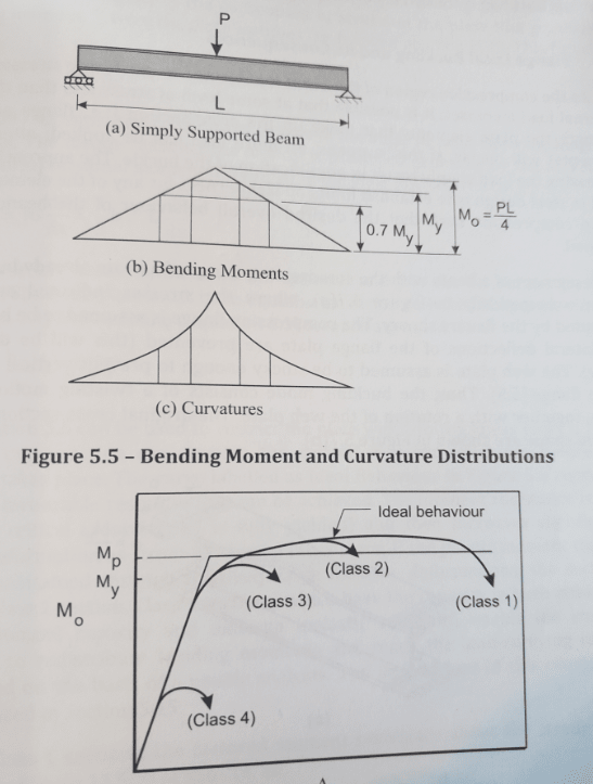
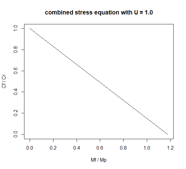
I think it's helpful to remember that even under so-called elastic loading (My), a beam would still be undergoing quazi-permanent deformation. In fact, deformation happens after only 70% of My. The thing is that

(A) it's really not a lot of deformation; and
(B) as dik notes, the actual service loads never really getting to the design loads (My or Mp depending on the case) given material reduction factors and loading factors

This allows us to assume an elastic response to an My loading +/- unless there are large compressive residual stresses in the flange tips. And we do.

Loadings_quucm0.png

Loadings2_ge3rjr.png


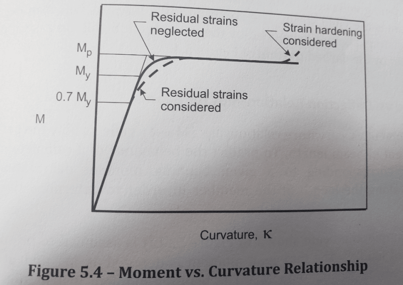
Now, for class 1/2 sections reaching Mp it's a bit harder to say that the deformation required to achieve Mp is negligible (as we did for My). But going back to what dik mentioned, I think the small shape factor (Mp / My) combined with large loading factors keeps service loads much closer to My and hence things, generally speaking, don't become overly deformed even if designed to be (see above for My deformations being negligible).

Typical Shape Factor = 1.12 (W310x52) to 1.18 (W610x551)
Typical Loading Factors = 1.25 (Dead Loading) to 1.5 (Live or variable Loading)

Now, it isn't quite a 1:1 comparison because the loading factors take into account the statistical nature of load and the idealized nature of it in design (e.g. uniform when not really). But it does go to dik's point that since the lowest typical loading factors is ~ 67% larger than the average Shape Factor (1.25 / 1.15) it seems reasonable to say that, on average, even if we design with Mp we are unlikely to get there in service.

RE: Beam-Column Design

I think it's the above that is keeping our beam columns from becoming unduly deformed in service rather than the U factor as you suggest. Lets take a look at a simple strong-axis bending + axial load case.

U1x = w / 1 - (Cf/Ce)

Well, w can be taken as 1.0 (13.8.5.b), and Ce is a function of member length. So we can arrange our example such that Cf = Cr << Ce by manipulating length of the member. And hence U1x = 1.0 (not punitive at all). For example, a W310x74 with K=1, Lu = 1250mm -> Cr = Cf = 2820kN << Ce = 206,972kN -> ~ U1x = 1.0

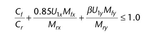
So our design equation reduces to,

(Cf / Phi*A*Fy) + (0.85*Mf / Phi*Z*Fy) <= 1.0

The code as far as I can tell, never says a thing about transient loading states for a beam column. In other words, it is code compliant (maybe not a good idea but that's another thing) to have a beam that acts as a pure flexure member, pure axial member, and a combined member at various points in time during service as long as it (A) satisfies the individual equations when under pure loading and (B) satisfies the combined equation under combined loading. It should be noted that (0.85*Mf / Phi*Z*Fy) <= 1.0 in the combined equation will always be satisfied if Mf = Mr = Mp for a transient pure flexure state.

What I am getting at here, is if the beam-column was once used in pure flexure with Mr = Mp prior to being used as a beam-column at some later point (intentionally) then the code allows for this despite that beam perhaps having undergone permanent deformation! The code does not explicitly, nor by the U factor (as we saw above), necessarily take these deformations into account and that is likely to pose an issue under heavy(ish) axial loading as KootK notes.

Realistically what is happening is service loads never get near actuals loads required to produce large, permanent deformation. And I think we have just been going along with it for so long, and that it has been satisfactory to this point, that really no change has been warranted.

IMHO I would probably keep Mr = My for a beam-column (especially one that has transient states) even if I could get more out of the code. Again, the savings are minimal (shape factor = 1.15) but possibility for bad things quite high. Not a good trade-off!
 
dik said:
At service loads, I'm pretty sure that all elements remain elastic, or nearly elastic even with plastic design.

Enable said:
(B) as dik notes, the actual service loads never really getting to the design loads (My or Mp depending on the case) given material reduction factors and loading factors

Gentlemen:

I believe that those statements, which underpin most of the arguments in your latest posts, are spurious. It does not matter that service loads may not result in elastic stress limits being exceed. We design for ULS loads and have to consider what is happening at that level.
 
My contention was that your contention (LOL) about deformation being taken into account by a "punitive" U factor in the combined stress equation was wrong and I have shown that to at least my satisfaction. The combined stress equation doesn't seem to take into account permanent deformation in beam-columns if loading conditions have been state-transient over time. And the reason why this has not been a problem is likely due to loads never reaching near enough the design capacity. That really shouldn't be contentious as the probability distributions are set that way (upper tail of strength overlapping with bottom tail of resistance only a small % of the time but largely no overlap).

That's surely different than saying one should have that headspace when designing. Of course we must use good engineering judgement and perhaps we should use My even if Mp is permissible when looking at beam columns.
 
Enable said:
your contention (LOL) about deformation being taken into account by a "punitive" U factor in the combined stress equation

It wasn't my contention that permanent deformation was being taken into account by the U-factors. Rather, it was my contention that U-factors, in the presence of significant axial load, may amplify the moments to the extent that they never actually see My/Mp even at ULS load. Just one possible hypothesis.

In my book, the code beam column checks simply do not apply to a member that has experienced permanent set of any kind or at any time because that permanent set implies a baked in P-baby-delta in excess of that considered by the design procedure. After permanent set, your code Cr & Mr_LTB estimates are junk. One might adapt the design procedure to account for such a strain history but I see nothing that leads me to believe that it's already incorporated into the CSA S-16 stuff.

Enable said:
And the reason why this has not been a problem is likely due to loads never reaching near enough the design capacity. That really shouldn't be contentious as the probability distributions are set that way (upper tail of strength overlapping with bottom tail of resistance only a small % of the time but largely no overlap).

I think that's crazy talk. Effectively: it should be fine at ULS because, stochastically, it will never reach ULS.
 
No question about it Koot... just lurking in the back of my mind... nearly always... not spurious at all. As I noted for normal loading, the shape factor for Zx is approx 1.15 x Sx... this helps ensure the structure is in the elastic zone. The added strength is greater than the load factor. In the event you get the full design loading (including load factor effects) you can go into the plastic region, in particular, if you have taken advantage of plastic hinge formation... it's really uncommon in practice for steel framing to go there... there is a high reliabilty for the strength of steel framing (not necessary for the loading or how it acts). I'm comfortable with it... the only fly in the ointment as below...

Enable: the only 'tricky' part about plastic design is related to your comment about residual stresses from overloading (yes Koot, there sometimes are residual stresses and they have to be considered)... there is a catchy problem that comes from the residual stresses and reverse loading called 'shakedown'... generally my only concern. My first exposure to them was in Massonette and Save's text from 50 years back, and later in Baker's Steel Skeleton... both, some of the better references I've encountered.

Rather than think climate change and the corona virus as science, think of it as the wrath of God. Feel any better?

-Dik
 
I should have added, Koot... that it's safe at ULS, too... I never design for loads that will never be achieved... nor do I hedge my bets on it... beyond the elastic range, members can still safely support increasing load... just consider the fixed end beam (classic example)... it can be safely loaded well beyond the point where supports have gone into the plastic moment range.

Rather than think climate change and the corona virus as science, think of it as the wrath of God. Feel any better?

-Dik
 
KootK: So we agree that the combined stress equation doesn't take it into account explicitly (obviously). But you posit that it might be implicitly taken into account by limiting the Mf / Mr term via an interaction with U in the presence of some axial load. Meaning, it's a nothing burger because it's never seen. I disagree with that as a simple example shows:

Take my above example of a W310x74 with K=1, Lu = 1250mm -> Cr = 2820kN << Ce = 206,972kN -> ~ U1x = 1.0

The U-factor is doing nothing here because even with Cf ~= Cr -> U1x ~ 1.0.

Lets say that we have Cf = 0.10*Cr. What happens to the flexure component? Well it's a C1 section so Mr = Mp. We get,

0.10 * (Cr /Cr) + 0.85 * 1.0 * Mp / Mp <= 1.0 ----> 0.95 <= 1.0 TRUE

This is a realistic design example where the plastic moment is allowed to occur by the combined stress equation even without transient states being considered. Moreover, in the presence of high axial load the U factor wouldn't limit Mf it would simply be the Cf/Cr term that does the job.

All I am saying is that this equation, neither explicitly nor implicitly via the U-factor or otherwise, necessarily limits the design moment to being less than Mp. That is to say nothing of transient states which are not explicitly prohibited. Note: I am not saying I advocate designing this way just that I think it's quite grey as to if the code allows for it or not.

kootK said:
I think that's crazy talk. Effectively: it should be fine at ULS because, stochastically, it will never reach ULS.
I have to again disagree. That's not a crazy thing to say at all! Limits states is an inherently statistical procedure that uses equating of experimentally/empirically derived probability distributions for resistance and loading to tolerance thresholds for failure. In the construction of Limits States it is known and accepted that there is some probability of failure. There has to be. The idea is just that it is low enough relative to our tolerance given (A) satisfactory past performance and (B) economics.

EDIT - ULS is not a number it's a design envelope that is intended to ensure a certain (low) probability of failure. So it is entirely consistent to say that something is likely not to fail because the loads will be unlikely to exceed certain thresholds in practice. That's the entire point of the design to begin with!

EDIT 2 - Hopefully what I am saying makes sense. I feel we might be talking past one another based on what we are both assuming / thinking about that is not explicated!

Code_Calibration_wvjvcy.png
 
dik said:
As I noted for normal loading, the shape factor for Zx is approx 1.15 x Sx... this helps ensure the structure is in the elastic zone.

I fail to see how the shape factors helps anything. Does one not design elastically with Sx and plastically with Zx such that the shape factor is already baked into whatever design approach is chosen? If so, then the fact that [Zx / Sx > 1] changes nothing.

dik said:
... there is a high reliabilty for the strength of steel framing (not necessary for the loading or how it acts). I'm comfortable with it...

Again with the crazy talk. The reliability of both the loads and the material properties are baked into the code design methods. They're not there for you to mess with. If you're comfortable messing with them anyhow, that's your prerogative. But you can't rationally claim to be in compliance with the design standard following that approach.
 
To kind of summarize my previous post in terms of the combined stress equation

1 - Mf is not limited to being less than Mp necessarily
2 - To the extent that it is, it is Cf / Cr and not the U factors that generally accomplish this (though U factors may play a roll sometimes)
3 - It is ambiguous as to whether or not the equation is intended to hold over transient loading states for the same member (even if the member is considered a beam-column throughout its existence). I think engineering judgement is required here and that KootK is correct that if you believe the beam-column to plastify at any particular point you better account for additional issues with the load path or else size so that this doesnt happen.
4 - We already live with a tiny bit of deformation when designing to My, even if we dont recognize it in the formalism. So some deformation is not the end of the world.

KootK would you now agree with this?
 
Enable said:
Take my above example of a W310x74 with K=1, Lu = 1250mm -> Cr = 2820kN << Ce = 206,972kN -> ~ U1x = 1.0

What kind of an example is a 4' column that basically reaches it's squash load (300 MPa) and has a kL/r of 25? That's the furthest thing from a meaningful beam column example.

Enable said:
Lets say that we have Cf = 0.10*Cr. What happens to the flexure component?

Again, you're talking about levels of axial load so insignificant that, in concrete, we'd often not even bother to consider them.

Enable said:
Limits states is an inherently statistical procedure that uses equating of experimentally/empirically derived probability distributions for resistance and loading to tolerance thresholds for failure.

In the construction of Limits States it is known and accepted that there is some probability of failure.

Both of these statements are true. And both are already baked into our design procedures and thus not subject to designers messing with them.

Enable said:
So it is entirely consistent to say that something is likely not to fail because the loads will be unlikely to exceed certain thresholds in practice. That's the entire point of the design to begin with!

Yes, and that is again completely baked into our design procedures and, therefore, already exploited to its maximum potential. If you have reason to believe that the baked in probabilities are out of whack for a given situation, so be it. But to claim that such wiggle room exists in our default procedures is incorrect in my opinion. Fundamentally so.

What is it that you see as being the takeaway from the clip below? As far as I can tell, it just describes reliability a bit and notes that it's been baked into the latest bridge code. All of which would support my view of things.

CO1_z8ucig.png
 
Yikes, it seems like you are reading things not the way I have intended. Let me try to simplify:

You said

c) I suspect that, for significant axial loads, the factors that amplify the moments become so punitive that, in effect, they prevent the member from going plastic under the load combination being considered.


This is demonstrably false and what prompted my line of posts. U does not have to be punitive in presence of axial loads (though it can be). In the presence of high axial load the Cf / Cr term is sufficient to restrict Mf < Mp

Okay okay I'll admit the example was perhaps poorly chosen! Though go through the handbook and find a section you like and find to be realistic. Since Ce is a function of L it doesn't matter as U can be constructed to be 1.0.EDIT - Best way to see this is maybe not the example but by inspection of a graph with U = 1.0

Combined_Stress_Equation_gmu4ol.png


Sure lets agree 10% is trivial. At what point do you start to care about deformation? 30%? 40%? Look at the graph and for any Cf / Cr > 0.20 Mf never will approach Mp....so as long as less than 20% is co-called trivial, U doesn't have to do anything (it's at its lowest value in the graph). It's entirely the Cf / Cr term!

ULS not sure what picture is intended to show

Again, I don't think you understand what I am saying......I am not saying to CHANGE THE DESIGN based on the fact that loads in service are unlikely to reach what we design for BUT rather that there is a large number of structures in service that never see such loads even if designed for them and hence in practice the typical plastification issue you are bringing up here has not been a factor. And regardless of what goes on in the design, and what equations you use, this is going to be true.

KootK said:
I'm afraid that I agree with very little of that.

Well, shucks. What can one say about that. In that case I doubt very much that we will converge our views so for my part I'll discontinue posting on this topic, as I don't want to needlessly clutter the forum.
 
Enable said:
This is demonstrably false and what prompted my line of posts. U does not have to be punitive in presence of axial loads (though it can be).

doesn't have to be punitive in the presence of all axial loads but will be in meaningful column buckling situations where Cf/Ce creeps up to meaningful values. I, for one, am not overly concerned with what happens with squash load columns like the one in your example.

Enable said:
In the presence of high axial load the Cf / Cr term is sufficient to restrict Mf < Mp

This sounds to me like my very own argument. Namely:

1) Flexural hinge formation is precluded somehow by the interaction equation.

2) You credit Cf/Cr which, just like my crediting the U-factors, is non rigorous in any mathematical / mechanics sense.

3) For a practical column of meaningful slenderness, Cf/Cr would only provide protection against flexual plastification IF the U-value properly amplifies Mf. Which takes us back to the U-factors being one valid way to consider how the interaction equation prevents plastification. It's equally valid to say:

a) Cf/Cr being large solves the problem and;

b) U x Mf / Mr being small solves the problem. For this version to work, a sufficiently high U-factor is necessary.

Enable said:
Though go through the handbook and find a section you like and find to be realistic. Since Ce is a function of L it doesn't matter as U can be constructed to be 1.0
.

The section isn't the problem. The problem is the section in combination with that ridiculously short, 4' unbraced length. Obviously, at meaningful unbraced lengths, the U-factor will be larger than 1.0 for any cross section. Otherwise, why have U-factors?

Enable said:
If a beam column starts out as lowly axially loaded but has a change of state to a higher axial condition it is not clear that the same equation is not intended to hold. If I am wrong please provide a code reference

I don't believe that I said that the interaction equation would not be valid for that situation. So long as the beam column were properly designed for the higher axial demand of the second case, I don't see why it would be a problem for it to first experience the lower axial demand of the first case. I don't require code references to think and discuss interesting engineering ideas.

Enable said:
Again, I don't think you understand what I am saying....I am not saying to CHANGE THE DESIGN based on the fact that loads in service are unlikely to reach what we design for..

I understand what you're saying now but, originally, you said this:

Enable said:
..as dik notes, the actual service loads never really getting to the design loads (My or Mp depending on the case) given material reduction factors and loading factors.
This allows us to assume an elastic response to an My loading +/- unless there are large compressive residual stresses in the flange tips. And we do.

That sounded to me like your were saying that SLS loads rarely reaching ULS load levels could be factored into how we do our ULS designs. That's what allows us to make that assumption that you mentioned.


@Enable: you're editing your posts substantially and faster than I can react to the changes. I'll let this sit for a day or two to congeal.
 
Strain hardening might be the margin of safety that's not being accounted for in this discussion. Stiffness is lost at yield but then there is a bit of recovery before it goes completely to soup.

I don't have the Canadian code so am curious if that 0.85*Mfx interaction factor is only allowed for symmetric, compact sections? It looks suspiciously like 1/1.18 in the Australian code.

Also, what's the beta factor in the Mfy part of the interaction equation?

Edit: And do you do moment magnification for P-smalldelta in your analysis, or is the U factor the only time within-span deflections are accounted for in this respect?
 
KootK said:
I think that's crazy talk. Effectively: it should be fine at ULS because, stochastically, it will never reach ULS.

It needn't be fine at ULS. ULS is loss of structural integrity. You need to remain below ULS. If you're unlucky enough to get the design (over)load and get the piece of steel that's understrength by the amount the code is based on, expect collapse.
 
steveh49 said:
It needn't be fine at ULS. ULS is loss of structural integrity. You need to remain below ULS. If you're unlucky enough to get the design (over)load and get the piece of steel that's understrength by the amount the code is based on, expect collapse.

I agree, of course, but I don't understand why you felt compelled to add that in response to my paraphrasing somebody else's argument that I don't agree with. Can you elaborate?

Also, for what it's worth, in North America it's typical to refer to the ULS load level and "factored loads" interchangeably.

See below for more information about the method being discussed. For members not falling into this category, the 0.85 goes away.

steveh49 said:
And do you do moment magnification for P-smalldelta in your analysis, or is the U factor the only time within-span deflections are accounted for in this respect?

Designer's choice I believe. That said, in my experience, most beam columns will be designed with the U-factor method of accounting for P-baby-delta.

Is 1.18 = 1/0.85 = a factor that accounts for strain hardening in the Australian code for stocky, symmetric shapes?

C01_lbik85.jpg
 
Status
Not open for further replies.

Part and Inventory Search

Sponsor

Back
Top