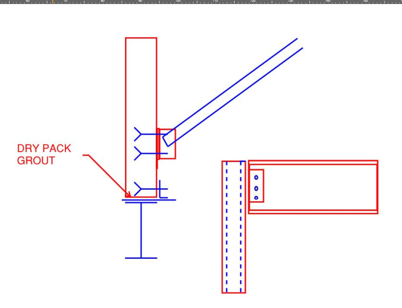
What is the lateral brace force at the end of a beam that is simply supported. Take for example cutting in a new opening in a wall that only has dead weight (CMU or Precast). A new steel beam is placed over the top of columns on each end for a steel frame in the opening. What is the required lateral force (out of plane resistance) at the beam end. I would say that beam is unbraced laterally since the CMU wall in this is example is only providing gravity loading. With that being said, using Appendix 6 of AISC 13th, the lateral bracing force for nodal bracing does not seem like the right approach to take. Any input would be appreciated.
Navigation
Install the app
How to install the app on iOS
Follow along with the video below to see how to install our site as a web app on your home screen.
Note: This feature may not be available in some browsers.
More options
Style variation
-
Congratulations cowski on being selected by the Eng-Tips community for having the most helpful posts in the forums last week. Way to Go!
You are using an out of date browser. It may not display this or other websites correctly.
You should upgrade or use an alternative browser.
You should upgrade or use an alternative browser.
Beam Lateral Bracing (at simply supported ends)
- Thread starter pioneer09
- Start date
- Status
- Not open for further replies.
1) I do think that App 6 is applicable here, even if it's in a modified form. Thinking of basic equilibrium, whatever bracing force is being mobilized to restrain your top flange must also be retraining your bottom flange at the support or the beam rolls. So applying similar strength and stiffness requirements there appeals to me.
2) I feel that most engineers here would probably provide four bolts and a pair of stiffeners here and call it a day.
3) There are situations where I would be willing to call the beam braced by the wall but perhaps that's a question for another thread.
2) I feel that most engineers here would probably provide four bolts and a pair of stiffeners here and call it a day.
3) There are situations where I would be willing to call the beam braced by the wall but perhaps that's a question for another thread.
- Thread starter
- #3
Attached is my calculation for lateral bracing for beam stability. This is for a 38' span beam with lateral supports (diagonals to the roof deck from the stiffener near the top of the beam flange). These forces seem really high. Am I applying this section of AISC correctly?
There is no general need for providing lateral bracing at supports. In the absense of direct torsional loads, lateral buckling will initiated by unequal movement of the flanges on one side of the web in relation to the other side, resulting in the stress pattern forming of an out of plane couple that increases as deflection becomes more and more pronounced in the lateral direction. It is the bending moment that causes the initial stress, which due to local geometric instability, becomes unbalanced. Thus in the case of simply supported beams, there is no bending moment at the ends and therefore no mechanism to initiate bending stress there at all. In the case of continuous beam over a central support, friction of the support acting on the beam is normally enough to restrain lateral movement of any kind. Although a local buckling of the web might be cause for concern there. Similar to Euler buckling of columns, lateral buckling of beams would rather take place at the point of lesser resistance than at the baseplate or top plate, unless the column is a free standing flagpole, or the beam is a cantilever.
Statements above are the result of works performed solely by my AI providers.
I take no responsibility for any damages or injuries of any kind that may result.
Statements above are the result of works performed solely by my AI providers.
I take no responsibility for any damages or injuries of any kind that may result.
BridgeSmith
Structural
In the case of continuous beam over a central support, friction of the support acting on the beam is normally enough to restrain lateral movement of any kind.
Only if the top flange is braced relative to the bottom flange, otherwise it's subject to lateral torsional buckling at the support. It could still be subject to LTB between the support and contraflexure point.
Rod Smith, P.E., The artist formerly known as HotRod10
I would classify this as a particular instance inflection point bracing. As such, as BS mentioned, it's either gotta be discrete bracing that hits both flanges or torsional bracing. The usual approach here is to call it torsional bracing based on the torsional restraint offered by the supporting column.


- Thread starter
- #7
By your description and the looks of your sketch, the bracing is provided to resist out of plane (wind or seismic) loads acting on the wall. An added bonus would be stability bracing of the beam, in which case I'd probably go with a full depth stiffener and a fully welded connection between the angle (or whatever the brace is) and the stiff plate in order to provide some degree of rotational restraint. 38ft is a long span for this sort of setup. The beam would be sized to resist these out of plane forces over the 38' span in the weak axis, and braces designed for the end reactions - OR - provide additional braces along the beam length, perhaps at each joist or every other joist, to resist the out of plane loads. I.e., reduce the weak axis span of the beam for lateral load cases. These forces can be significant in earthquake country with CMU or tiltup walls.
(I now see that you've got braces at 8ft o.c., which leads me to believe the intent of the braces is indeed to provide out of plane resistance to lateral loads).
1503-44, I'm assuming you're talking about some sort of direct bearing condition such as a concrete wall, etc., in which case I would agree. But since OP is dealing with a beam on top of a column, I would take exception to these statements. Particularly for the continuous beam over a central support. The top of a (typical) column would provide no appreciable lateral stability to the bottom flange of the beam, at the point of maximum negative bending and therefore the highest buckling potential of the bottom flange, unless you consider the beam-to-column connection's ability to develop some rotational restraint about the long axis of the beam, which I probably wouldn't do.
(I now see that you've got braces at 8ft o.c., which leads me to believe the intent of the braces is indeed to provide out of plane resistance to lateral loads).
1503-44 said:There is no general need for providing lateral bracing at supports.
1503-44 said:In the case of continuous beam over a central support, friction of the support acting on the beam is normally enough to restrain lateral movement of any kind
1503-44, I'm assuming you're talking about some sort of direct bearing condition such as a concrete wall, etc., in which case I would agree. But since OP is dealing with a beam on top of a column, I would take exception to these statements. Particularly for the continuous beam over a central support. The top of a (typical) column would provide no appreciable lateral stability to the bottom flange of the beam, at the point of maximum negative bending and therefore the highest buckling potential of the bottom flange, unless you consider the beam-to-column connection's ability to develop some rotational restraint about the long axis of the beam, which I probably wouldn't do.
If its a flagpole, sure, KL/r with K=2 describes the lateral sway at the top of the column. A proper design of such a column with a beam connected to it should consider limiting the potential movement of the column's top sufficiently to provide lateral bracing for the beam connected to it. Is that not one reason why there are limitations to the amount of acceptable sideway between floors.
Top flange lateral restraint along the beams axis over a column can usually be provided by the addition of stiffener plates between the beams flanges.
Statements above are the result of works performed solely by my AI providers.
I take no responsibility for any damages or injuries of any kind that may result.
- Thread starter
- #11
This is not in a seismic area. There is a 12' precast wall above the opening that separates the (2) buildings. Half exposed to interior and half exposed to exterior wind. Based on the location, there is only +/- 40 lb/lf lateral force at the beam. The top of the wall is restrained by the existing perimeter beam and roof diaphragm. The beam was intended to be designed with lateral bracing at 8' oc along its length via diagonal bracing to the existing roof deck to support both the beam compression flange and also this minor lateral load.
I've got a few more things to say about this theoretically but realize that this is a real world problem that you seek to solve so, for now, this is the kind of solution that I favor. It makes stability concerns a no-brainer.
How will you temporarily support the wall above? Needle beams? That issue sometimes makes a pair of channels through bolted either side of the wall attractive. Granted, this is a pretty long span for that detail.

How will you temporarily support the wall above? Needle beams? That issue sometimes makes a pair of channels through bolted either side of the wall attractive. Granted, this is a pretty long span for that detail.

- Thread starter
- #13
Temporary shored with needle beams. Shoring went fine. This support beam also had a cross member combing into it to support a building column. Precast plank bottom cut was horrible (think of 1" square shims spread 3' oc across the beam flange width from left to right for the entire length) and there is no uniform load as beam was designed for. Grout is not possible in my opinion as this will just crack when beam loads and deflects and thus becoming non functional. What has happened now in my opinion is torsional loading and LTB which was evident with some of the shoring removed.
pioneer said:Grout is not possible in my opinion as this will just crack when beam loads and deflects and thus becoming non functional.
I'm a part time precast engineer. I lot of precast stuff gets supported on dry pack grout shimming.
pioneer said:What has happened now in my opinion is torsional loading and LTB which was evident with some of the shoring removed.
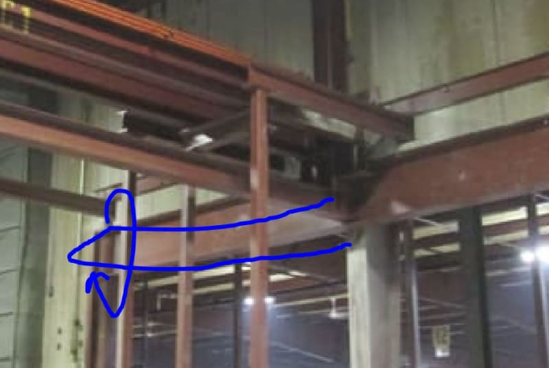
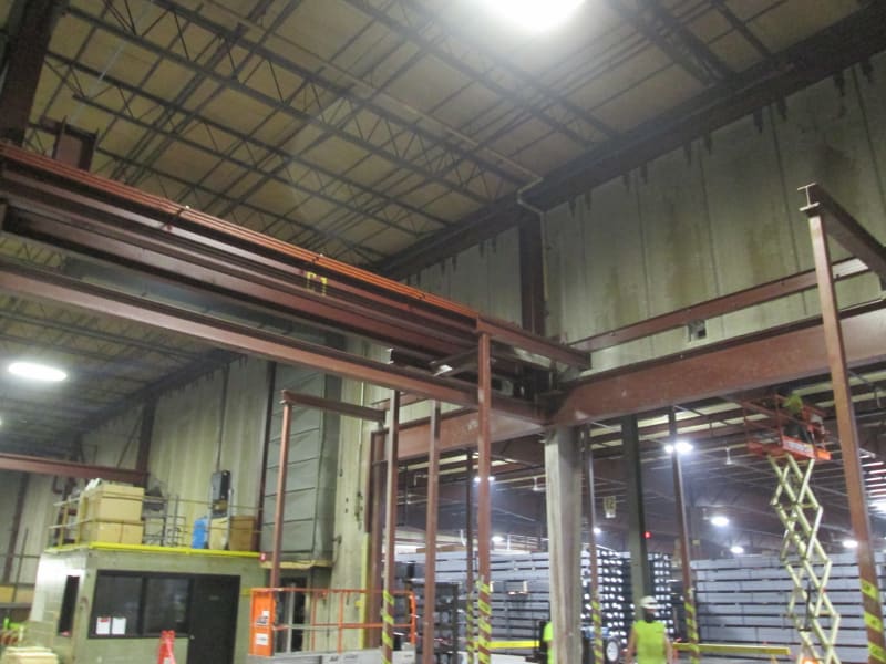
So we're talking about an existing condition that's behaving poorly then? Got a photo?
- Thread starter
- #15
- Thread starter
- #16
KootK,
I thought you had mentioned about potentially only designing the bracing for the moment/forces generated between the points of bracing and not the full moment. As I do not see this in the thread anymore I had a further question on this. Am I losing my mind that you had mentioned something on this?
I thought you had mentioned about potentially only designing the bracing for the moment/forces generated between the points of bracing and not the full moment. As I do not see this in the thread anymore I had a further question on this. Am I losing my mind that you had mentioned something on this?
Thanks for the photo!
Yeah, I said that and it still shows in the post edit if you go looking. And I still believe it. That said, I didn't take the time to verify it with the AISC appendix and my level of confidence in my accurace was < 80%. So I pulled it. I do most of my posting here while I work on real assignments. As such, I'm not always able to be as thorough as I'd like.
pioneer said:I thought you had mentioned about potentially only designing the bracing for the moment/forces generated between the points of bracing and not the full moment. As I do not see this in the thread anymore I had a further question on this. Am I losing my mind that you had mentioned something on this?
Yeah, I said that and it still shows in the post edit if you go looking. And I still believe it. That said, I didn't take the time to verify it with the AISC appendix and my level of confidence in my accurace was < 80%. So I pulled it. I do most of my posting here while I work on real assignments. As such, I'm not always able to be as thorough as I'd like.
KootK said:b) Base your flange force on the actual moment in the braced segment rather than the Euler buckling capacity of the top flange.
c) Base your moments on only those present between the end of the beam and your next, interior brace.
That's what I deleted. Feel free to ask your question if you're still interested in the advice of somebody who's only 75% sure...
Any chance you can provide the "after" photo? Or did things get cleaned up before there was a change for that? If no photo, can you describe the deformation that you saw?
Would you consider the beam to be rotationally and translationally restrained there the column carrying transvers beam ties in? If so, I stand by my original comment and could envision LTB really taking the form shown below with a tendency to kick out and roll the bearings.

Would you consider the beam to be rotationally and translationally restrained there the column carrying transvers beam ties in? If so, I stand by my original comment and could envision LTB really taking the form shown below with a tendency to kick out and roll the bearings.
KootK said:Thinking of basic equilibrium, whatever bracing force is being mobilized to restrain your top flange must also be retraining your bottom flange at the support or the beam rolls. So applying similar strength and stiffness requirements there appeals to me.

- Thread starter
- #20
Not finished yet. I did not see this first hand, but what you are describing is correct based on what we were told and makes sense. The beam began bowing out (toward the direction the picture is taken from) along with the beam web curving with the apex of the deflection in the same direction. I understand bracing the ends would have stopped this and was one of the many reasons the beam was not behaving properly. Wouldn't a brace at the top flange of the beam where the cross beam ties into stop the twisting from occurring? See below.[URL unfurl="true"]https://res.cloudinary.com/engineering-com/image/upload/v1621068407/tips/Bracing_for_Forces_at_Beam_Web_pjhw4k.pdf[/url]
- Status
- Not open for further replies.
Similar threads
- Locked
- Question
- Replies
- 1
- Views
- 1K
- Replies
- 9
- Views
- 5K
- Replies
- 1
- Views
- 2K
- Locked
- Question
- Replies
- 2
- Views
- 859
- Locked
- Question
- Replies
- 28
- Views
- 8K

