Eng-Tips is the largest engineering community on the Internet

Intelligent Work Forums for Engineering Professionals

beam load off center 3

CPBe

Structural
Nov 4, 2019
16
0
0
US
Have an issue with a large piece of equipment sitting off the web of the main support beam - see sketch below:
CT.load-off.ctr_jb9hum.jpg

Field crew claims the web is bending inward along with the top flange, and the member isn't even fully loaded yet.
What, in your opinion, would be the most economical approach to rectifying this issue?
Would, say, full-height stiffener plates along the beam's length (under the unit) make the most sense? Or maybe a channel member along the outside (accessible) portion of the beam?
Any advice/insight would be greatly appreciated.
Thank you in advance for your help!
 
Replies continue below

Recommended for you

KootK: Yes - equipment could be removed.
SWComposites: Could you please point me in the right direction for the most straight-forward approach of sizing & spacing transverse stiffeners? (Also, would stiffeners on the left side provide much benefit in this scenario?)
 
I've attached a basic flowchart for transverse stiffener design. You might be able to size the stiffener for strength only considering the contribution from one side. However, your situation seems to be more of a serviceability/deformation issue that's affecting performance.

Stiffening on the left side would help activate the whole cross section in resisting the torsion and provide a load path to the dampener other than flexure of the left-side bottom flange.

In any case, the old adage, "when in doubt, make it stout" applies. It's always good to stiffen beams under concentrated loads, especially at beam ends.
 
 https://files.engineering.com/getfile.aspx?folder=9430e2c7-84fa-4c99-86a3-4cbf22e53859&file=Basic_Stiffener.pdf
To me, the description of the movement sounds less like cross section distortion and more like pure torsion/twist. If it is torsion/twist, I would not expect stiffeners to be very effective. Instead, I would focus on making effective roll beams out any transverse framing present. And perhaps adding more.

A plan view of the situation would be useful
 
Here's a plan view (red lines indicate outline & bolt pattern of equipment):
CT.plan_svnvaq.jpg

(Overall dim's are approximately 33'x21')
Planning on visiting the site later today to get more info.
Thank you all for your help, I really appreciate it!
 
not my field (so tell me to shut up) ...
1) is that small transverse beam fixed onto the larger beam ? I know we'd normally assume pinned (conservative for the beam, not so conservative for the end attachments). That would push more torsion into the joint.

2) what sort of shear is being applied ?

3) the question is "is the web deforming due to the offset shear (in which case stiffeners would help the web) or is it torsion on the section (so the whole section is twisting, something you can check) then you'd need something to make the large beam more effective in torsion (like a 2nd web to make an enclosed box area)

"Wir hoffen, dass dieses Mal alles gut gehen wird!"
General Paulus, Nov 1942, outside Stalingrad after the launch of Operation Uranus.
 
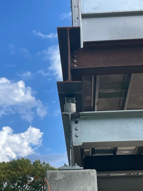
Update: after visiting the site the issue isn't entirely clear, but there are some more variables to consider.
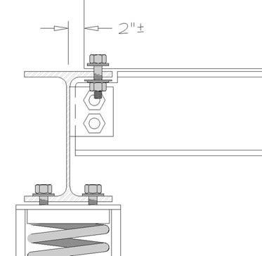
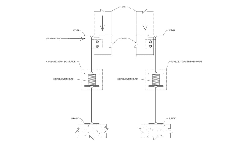
1) There are springs between the unit support steel & the steel anchored to the concrete footings; springs are only about 5"wide, and the b[sub]f[/sub] of the unit support steel is 10"w
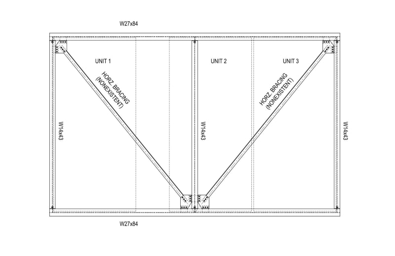
2) The entire support assembly was shipped with welded plates at each corner - the contractor reached out us after removing one of said plates & noticed the steel frame "racking"
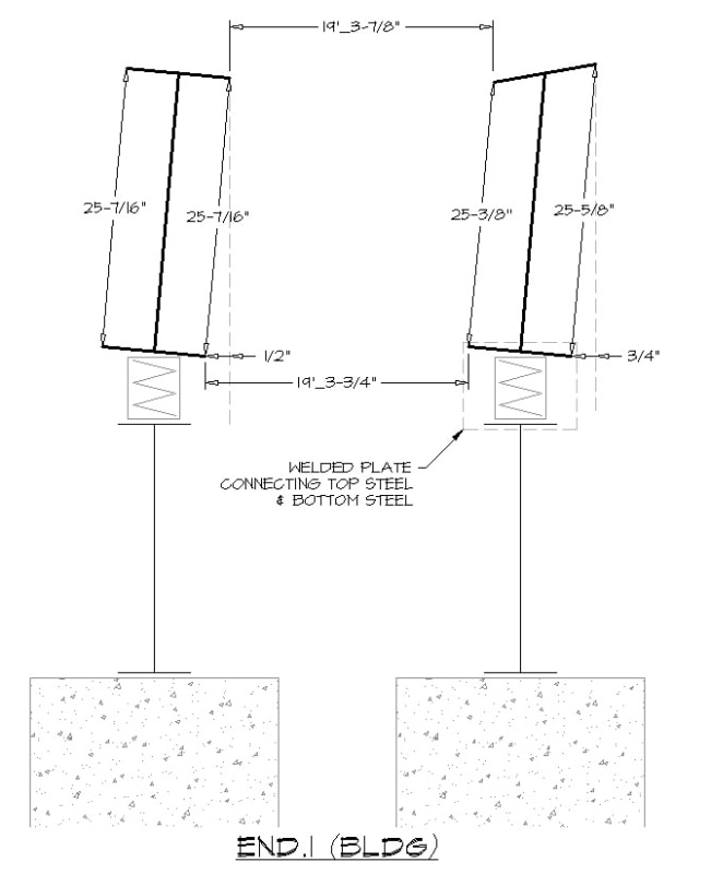
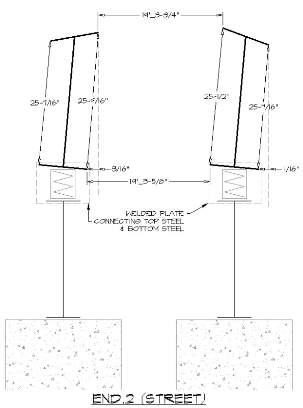
3) Measurements that were taken don't quite jibe with what was expected - they were taken at each end & the center, and each location indicates a somewhat different scenario (?)
a) end.1 _ beam to beam top flanges distance measurement is 1/8" longer than the bottom flanges measurement
one beam showed the inside height (d-2t[sub]f[/sub]) to be nearly 1/4" shorter on the inside of the frame
both of the top flanges appeared to lean to one side - one @ 1/2"offset & the other @ 3/4"offset​
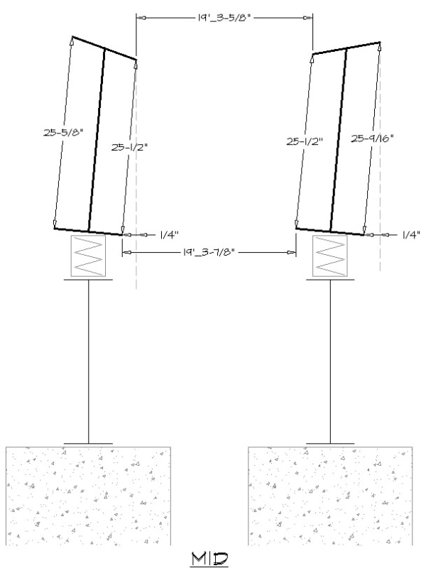
b) mid _ beam to beam top flanges distance measurement is 1/4" shorter than the bottom flanges measurement
both beams showed the inside height to be nearly 1/8" shorter on the inside of the frame
both of the top flanges appeared to lean 1/4" the same direction​
c) end.2 _ beam to beam top flanges distance is 1/8" longer than the bottom
both beams showed the inside height to be nearly 1/8" taller on the inside of the frame
both of the top flanges appear to lean nearly 1/8" the same direction​
I've included an exaggerated sketch of each scenario below to help clarify:
CT_end.1_eanlku.jpg

CT_mid_fulvao.jpg

CT_end.2_uhjqhq.jpg

Do you feel removing the welded plates on the remaining corners would let the frame "settle", or would it only make matters worse?
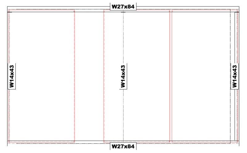
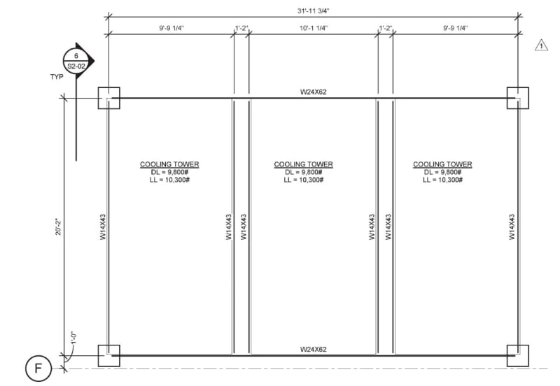
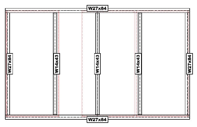
rb1957: 1) the 3 transverse beams are bolted onto a welded shear plate/angle; 2) design load along each W27 is approximately 1.2k/ft; 3) I was initially convinced the offset shear was the issue, now I'm not entirely sure...
Aesur: I believe there was an issue w/drain locations & placement of units, but calc's indicated an L[sub]B[/sub] of half the W27's length was enough to keep LTB in check
Removing the units to reinforce the steel is certainly not desired (though I'm sure if push came to shove, it would happen), but the contractor indicated they could at least ease the load during reinforcement.
Welding stiffener plates sounded like the desired approach, but maybe a few additional stabilizing members is a more sound approach (?)
Let me know your thoughts.
And thank you all for your input! Truly appreciated!
 
I don't mean to be obtuse, but why wouldn't a frame composed of (2) W27x84's, on springs, w/ (3) perpendicular W14x43's (pinned conx's at ends to W27x84's) be expected to rack? Welded plates at the ends of the W27x84's aren't going to do much. The guys loading the heavy units onto the frame, with the crane, aren't going to be gentle. It's going to experience some significant horizontal loading.

Unless I'm missing something, it doesn't looks very horizontally stable.

I'm not a module guy, but I'd expect some sort of horizontal bracing or moment connections, like this sketch. Best of luck man.

Plan1_wrx2in.jpg


Section1_b0ijwl.jpg
 
I really think pictures of the actual piece of equipment or the at least a generic picture of the equipment and its role here would help. It is hard to advise without knowing more detail about the item.

DrZoidberWoop said:
Unless I'm missing something, it doesn't looks very horizontally stable.
Agreed but it is hard to really know with the limited information give about the equipment.

Given the dimensions shown I'd expect lateral restraints on the top and bottom I-beams since there are springs there, both I beams are slender unstiffened columns. with a pin (spring) in the middle.

Also given the springs and the heavy item, you would expect everthing else needs to be quite stiff as the springs are presumably isolating vibrations into our out of the equipment.
 
Here is the plan for the base steel (per structural):
CT.steel_structural_n81b7z.jpg

And here's a photo of the corner (w/removed steel plate):
thumbnail_image002_thylca.jpg

One though that was brought up was installing 2 additional W27s at each end & shifting the 2 W14s inward, similar to below:
CT.plan_modified_avbmli.jpg

This seems costly (and I'm somewhat doubtful it would resolve the issue at hand); I think I'm leaning towards DrZoidberWoop's suggestion of adding some horizontal bracing, along with some stiffener plates to account for the offset shear.
Thank you all for the help!
 
Seems to me like the lower frame should just have been removed from the get-go. You've got a stack of wobbly steel now and it looks like it is performing as one would expect a stack of wobbly steel to perform. I'm guessing the lower, older frame was simply left in place to save money / avoid re-routing piping, etc., and no longer serves any purpose?

I would add vertical bracing to stabilize this whole thing(plus horizontal bracing to prevent the local distortion, like Dr. Zoidberg suggested). That would likely transmit some vibration though.

Ideally you'd pull the units off and rebuild this thing, but that ship may have sailed. You've got a bit of a mess on your hands here, OP.
 
CPBe said:
I think I'm leaning towards DrZoidberWoop's suggestion of adding some horizontal bracing, along with some stiffener plates to account for the offset shear.

That still doesn't solve the vertical imbalance issue. Dold put it better that I could. It is a stack of wobbly steel at present.

Though I would used two sets of vertical bracing so the springs remain effective. An alternative would be full height cleat plates for the cross beams with welds locking the cross beams in place to create a moment connection rather than a pinned connnection.
 
are we taking bets on when this'll turn up in the "engineering disaster" forum ?

"Wir hoffen, dass dieses Mal alles gut gehen wird!"
General Paulus, Nov 1942, outside Stalingrad after the launch of Operation Uranus.
 
Didn't quite comprehend in the initial posts that it was beams stacked on beams, you can imagine my surprise scrolling down and realising that the steel equivalent of balancing a house of cards is going on

----------------------------------------------------------------------

Why yes, I do in fact have no idea what I'm talking about
 
To somewhat mitigate the pile on. To CPBe's credit, she/he seems to have listened and responded to those on site. He/she has also continued to engage with the forum crowd following the question. Hopefully this will be a good learning experience.

Most of us probably have some similar stories to tell regarding learning experiences. I prefer to learn from other people's mistakes, but I certainly have made some oversights, thankfully none of them serious.
 
notice the upper cross beam (the center of this issue, I think) has the upper cap cut away at the end, so unlikely to act as a fixed end beam, so now we have a web bending under the offset load (the original thought) so stiffening webs should help the bending of the web.

nothing will help the "house of cards".

"Wir hoffen, dass dieses Mal alles gut gehen wird!"
General Paulus, Nov 1942, outside Stalingrad after the launch of Operation Uranus.
 
Back
Top